Interactive Study Environment • APJ Abdul Kalam Technological University
KTU 2024 SCHEME6 CONTACT HOURSTHEORY MASTERCLASS
Module 1: Introduction and Application Layer
A textbook-rigorous, examination-focused interactive guide designed to teach you every single concept from absolute zero, explain every diagram from the PDF notes, and train you to write flawless 3-mark, 6-mark, and 9-mark KTU examination answers.
Scroll and read through your original 49-page lecture notes directly below, or reference them alongside each interactive concept in the study guide.
PART 01HIGH PRIORITY • 3M / 6M
Overview of the Internet, Networks & Switching
PDF Pages: 1 – 4
💡 What You Are Learning & Why It Matters
Before diving into protocols, we must understand the fundamental physical and logical anatomy of the Internet: what constitutes a network, how hosts connect via LANs and WANs, why switching is required, how circuit and packet switching operate, and how Internet Service Providers (ISPs) form the global backbone.
1. Basic Explanation: What is a Network & The Internet?
A network is an interconnection of a set of devices capable of communication. A device can be a host (end system such as a computer, laptop, smartphone, server, or security camera) or a connecting device (router, switch, or modem).
The Internet (short for internetwork) is literally a "network of networks." Billions of heterogeneous computing devices worldwide communicate across transmission media (wired cables like twisted-pair, coaxial, and optical fiber, or wireless media like radio and microwave).
Figure 1.1: The Internet as an Internetwork of Interconnected Devices (Page 1)
Exam Drawing Tip: Show end-systems (hosts) on the edge connected to connecting devices (switches, routers) in the core, joined by transmission media.
2. Technical Categories of Networks: LAN vs. WAN
Computer networks are fundamentally categorized based on their geographic span, ownership, and connectivity topology:
Parameter
Local Area Network (LAN)
Wide Area Network (WAN)
Geographical Span
Confined to a single office, building, or campus (a few meters to a kilometer).
Spans a town, city, state, country, or the entire globe.
Created and operated by communication companies (telecoms/ISPs) and leased.
Internal Types
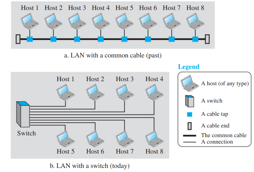
Common bus/cable (historic) or Link-layer switched (modern).
Point-to-Point WAN or Switched WAN.
Addressing
Each host has a unique link-layer hardware address (Physical / MAC address).
Hierarchical logical addressing (IP addresses and WAN link identifiers).
Data Rates & Delay
High data rates (typically 100 Mbps to 10 Gbps) and very low propagation delay.
Lower data rates compared to LANs and significant propagation delays.
Figure 1.2: Modern Switched LAN Architecture (Page 1)
A link-layer switch forwards packets only to the intended destination host based on its destination MAC address, preventing collisions and enabling multiple pairs of hosts to communicate simultaneously.
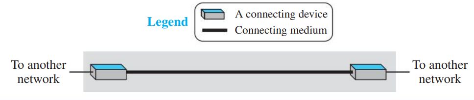
Figure 1.3: Point-to-Point WAN (Page 2)
Connects exactly two connecting devices via a dedicated transmission medium (cable or air) with no intermediate switches.
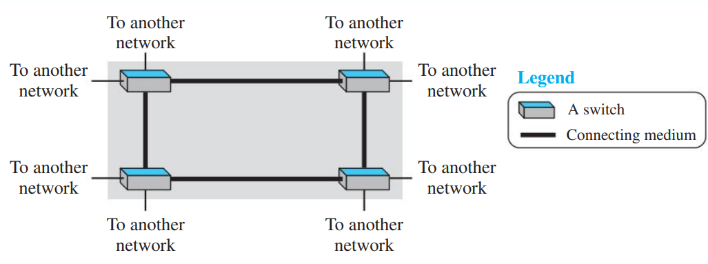
Figure 1.4: Switched WAN with Multiple Ends (Page 2)
Key Concept: A switched WAN consists of multiple point-to-point links joined by internal switches, forming a multi-point backbone capable of routing data across vast geographical distances.
3. Internetwork (Internet) & Connecting Topology
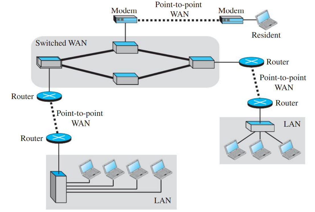
When two or more independent networks (such as two office LANs) are joined together, they form an internetwork. For instance, two office LANs can be interconnected using routers (R1 and R2) across a leased point-to-point WAN.
Same-office message: The local LAN switch delivers it directly to the local host; the boundary router blocks it from leaking outside.
Remote-office message: Router R1 intercepts it and routes it across the point-to-point WAN to router R2, which delivers it to the destination host.
Figure 1.5: Private Internetwork Connecting Two LANs via Routers (Page 2)
📐 High-Frequency KTU Formula: Full-Mesh WAN Links
If \(n\) independent LANs must be connected directly in pairs using dedicated point-to-point WAN links, the number of point-to-point WAN links \(W\) required is given by the combination formula:
\[W = \frac{n(n - 1)}{2}\]
Example: To connect 5 LANs in a full mesh requires \(W = \frac{5 \times 4}{2} = 10\) leased WAN lines. Because this scales quadratically as \(O(n^2)\), full-mesh connectivity is economically prohibitive. Therefore, networks are connected through switched backbones and routers.
Figure 1.6: Heterogeneous Internetwork with Routers and Switched WAN (Page 2)
4. Switching: Circuit-Switched vs. Packet-Switched Networks
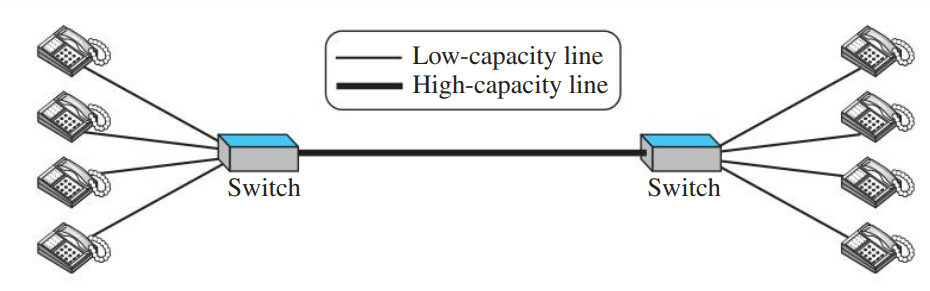
A switch connects two or more transmission links and forwards data between them. The two foundational switching paradigms are:
Feature
Circuit-Switched Network
Packet-Switched Network
Connection Setup
Mandatory dedicated physical path set up before data transfer begins.
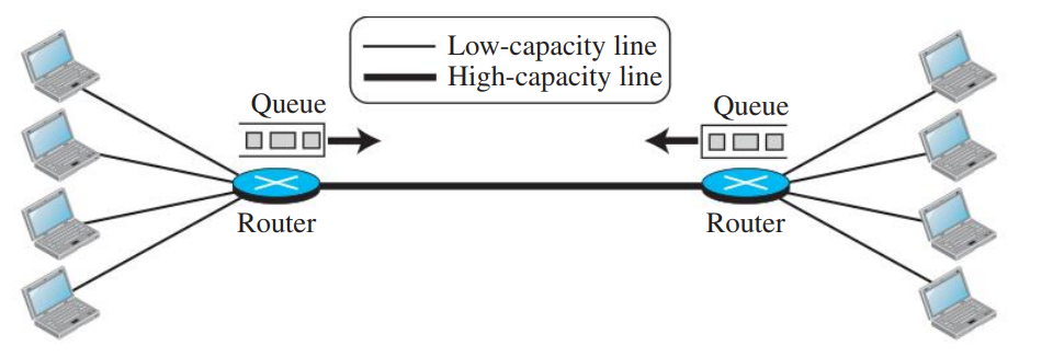
No pre-allocated dedicated circuit; data is broken into independent packets.
Resource Reservation
Full bandwidth is reserved for the duration of the call, even during silence.
Resources allocated on demand (statistical multiplexing / store-and-forward).
Packet Routing
All bits follow the exact same pre-allocated physical path.
Low bandwidth efficiency (wasted during idle periods).
High efficiency; bandwidth shared dynamically among many active users.
Delays
High setup delay, but zero queuing delay during active transfer.
Zero setup delay (in datagrams), but variable queuing and transmission delays.
Example
Traditional Public Switched Telephone Network (PSTN).
The Internet (IP network).
Figure 1.7: Circuit-Switched Network (Page 3)
Figure 1.8: Packet-Switched Network (Page 3)
Datagram Networks vs. Virtual-Circuit Networks
Datagram Network (Connectionless): Each packet (datagram) is treated as an independent unit containing full source and destination IP addresses. Intermediate routers make independent routing decisions for each packet. Packets may arrive out of order, be delayed, or be lost. The Internet Network Layer (IP) is a pure datagram network.
Virtual-Circuit Network (Connection-Oriented): A logical connection path is pre-established during a setup phase. All packets belonging to that session carry a short Virtual Circuit Identifier (VCI) and follow the exact same sequence of switches in order.
5. Structure of the Internet: ISP Hierarchy & Access Networks
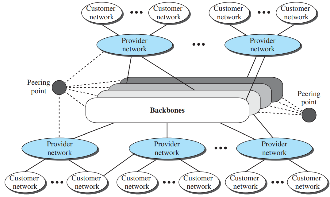
The global Internet is organized as a multi-tier hierarchy of Internet Service Providers (ISPs):
Backbone ISPs (Tier 1): International commercial providers (e.g., AT&T, Lumen, Tata Communications, NTT) that operate high-speed fiber-optic backbones spanning continents. They peer with one another at Peering Points / Internet Exchange Points (IXPs) without paying transit fees.
Provider Networks (Tier 2): National or regional ISPs that pay Tier 1 backbones for global reach and sell transit to customer networks.
Customer / Access ISPs (Tier 3): Local ISPs that directly connect end-user homes, universities, and businesses to the Internet.
Figure 1.9: Multi-Tier ISP Architecture and Peering Points (Page 4)
Access Technologies (Connecting to the ISP)
Dial-up Telephone Network: Uses an analog voice-band modem over traditional copper phone lines. Extremely slow (max 56 kbps); voice and data cannot be carried simultaneously.
Digital Subscriber Line (DSL): High-speed digital transmission over existing telephone copper wires using frequency division multiplexing (FDM), allowing voice and data to transmit simultaneously.
Cable Network: Uses the Community Antenna TV (CATV) coaxial cable infrastructure with a cable modem. High speed, but transmission medium is shared among residential neighbors.
Wireless Networks: Wireless LANs (Wi-Fi) for local mobility and cellular wireless WANs (4G/5G) for wide-area mobile Internet access.
Direct Leased Lines: High-bandwidth point-to-point connections (e.g., T1, T3, optical fiber) leased by large enterprises directly to a regional ISP.
📝 KTU Examination Model Questions & Answers (Part 1)
Model Answer:
Span: LAN covers a small geographic area (office, single building, campus), whereas WAN spans a town, state, country, or the world.
Interconnection: LAN interconnects hosts (end-systems) directly, whereas WAN interconnects connecting devices (switches, routers, modems).
Ownership: LAN is privately owned and maintained by an organization; WAN is created and maintained by telecommunication providers and leased to customers.
Solution:
Given number of nodes \(n = 6\).
Formula for full mesh point-to-point links:
\[W = \frac{n(n - 1)}{2} = \frac{6 \times (6 - 1)}{2} = \frac{30}{2} = 15 \text{ links.}\]
Therefore, 15 dedicated point-to-point WAN lines are required.
PART 02VERY HIGH PRIORITY • 5M / 9M ESSAY
Protocol Layering & The TCP/IP Protocol Suite
PDF Pages: 5 – 12
💡 Why Layering? The Foundation of Computer Networks
In a large network with millions of diverse computers, communication is immensely complex. Layering breaks this massive task into small, modular, independent layers. Each layer handles a single well-defined responsibility and offers services to the layer above it.
1. Principles & Scenario of Protocol Layering
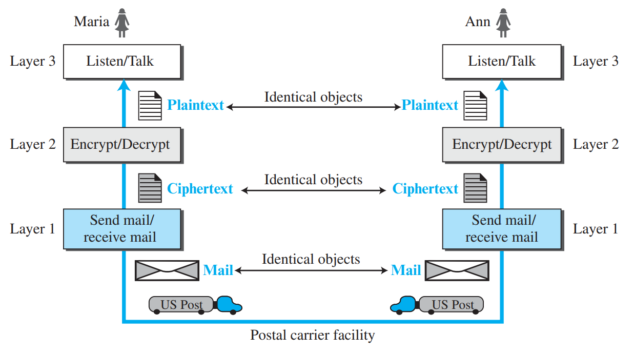
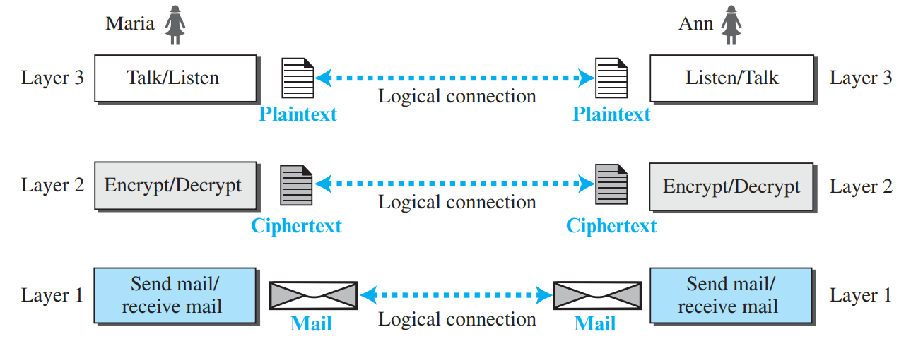
Consider the classic Maria and Ann scenario: Maria in India wants to send an encrypted confidential letter to Ann in America.
Layer 3 (Thought / Message Layer): Maria writes the plaintext letter. (At Ann's side, Ann reads the plaintext).
Layer 2 (Encryption / Translation Layer): Maria encrypts the plaintext into ciphertext. (At Ann's side, Ann decrypts ciphertext to plaintext).
Layer 1 (Physical Delivery Layer): The encrypted letter is handed to the postal carrier / mail transport service.
Figure 2.1: Maria and Ann Three-Layer Communication Analogy (Page 5)
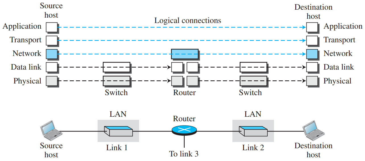
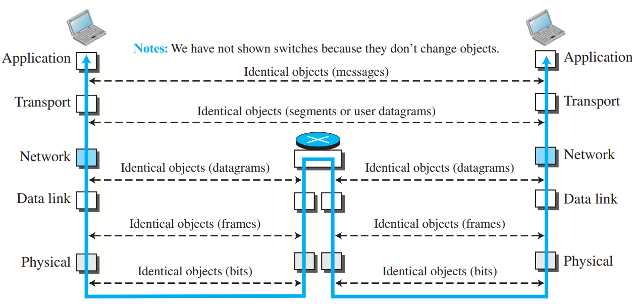
Figure 2.2: Logical Connections (Dotted) vs Real Path (Solid) (Page 5)
⭐ Two Fundamental Principles of Protocol Layering
Bidirectional Communication: If we want bidirectional communication, each layer at the sender must perform the exact inverse operation of the corresponding layer at the receiver.
Identical Objects: The two objects under each layer at both communication endpoints must be identical. For example, below Layer 3 is plaintext, below Layer 2 is ciphertext, and below Layer 1 is the physical parcel.
2. The Five-Layer TCP/IP Protocol Suite
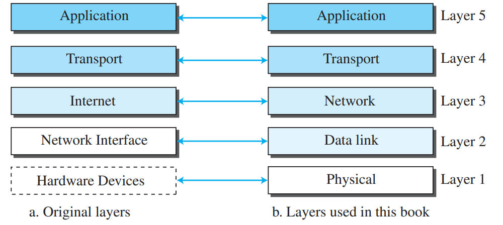
The original TCP/IP protocol suite defined a 4-layer architecture (RFC 1122: Link, Network, Transport, Application). Modern textbooks (Forouzan) present the standard five-layer model:
Figure 2.3: (a) Original 4-Layer TCP/IP Architecture vs (b) Modern 5-Layer Model (Page 6)
Layer
Protocol Data Unit (PDU)
Primary Responsibilities
Key Protocols
5. Application Layer
Message
Provides network services directly to user applications; handles high-level user communication.
HTTP, SMTP, FTP, TELNET, SSH, SNMP, DNS, IGMP
4. Transport Layer
Segment (TCP) / User Datagram (UDP)
Process-to-process logical communication, error control, flow control, and port addressing.
TCP, UDP, SCTP
3. Network Layer
Datagram / Packet
Host-to-host communication, logical addressing (IP), packet routing, and forwarding across networks.
IPv4, IPv6, ICMP, IGMP, OSPF, BGP
2. Data Link Layer
Frame
Node-to-node (hop-to-hop) frame delivery across a single physical link, physical/MAC addressing, error detection.
Ethernet (802.3), Wi-Fi (802.11), PPP, ARP
1. Physical Layer
Bits
Transmits individual raw bits over a physical transmission medium (electrical voltages, light pulses, or radio waves).
RS-232, 1000BASE-T, DSL, Fiber optics
Comprehensive Table: Protocols and Their Uses (PDF Page 8)
Protocol
Layer
Standard Purpose & Use
HTTP
Application
Accessing the World Wide Web and web documents.
SMTP
Application
Transferring electronic mail between mail servers.
FTP
Application
Interactive file transfer between client and server.
TELNET / SSH
Application
Remote terminal access and secure shell login.
SNMP
Application
Network management and monitoring of network devices.
DNS
Application
Finding the network-layer IP address from a human-readable domain name.
TCP
Transport
Connection-oriented, reliable, byte-stream transmission with flow and congestion control.
UDP
Transport
Connectionless, lightweight, low-overhead transport (DNS, VoIP, video streaming).
SCTP
Transport
Stream Control Transmission Protocol; supports multi-streaming and multi-homing.
IP (IPv4 / IPv6)
Network
Best-effort, connectionless host-to-host packet delivery and logical addressing.
ICMP
Network
Internet Control Message Protocol; error reporting and network diagnostics (e.g., ping).
IGMP
Network
Internet Group Management Protocol; manages multicast group membership.
3. Layers in Network Devices & End-to-End vs. Hop-to-Hop
Not all devices implement all five layers:
End Hosts (Computers, Phones, Web Servers): Run all 5 layers.
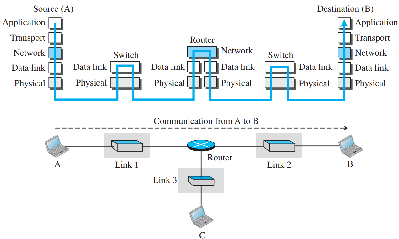
Routers: Operate at 3 layers (Physical, Data Link, and Network) to route packets based on IP addresses.
Link-Layer Switches: Operate at 2 layers (Physical and Data Link) to forward frames based on MAC addresses.
Figure 2.4: Layers in Hosts (5), Routers (3), and Switches (2) (Page 6)
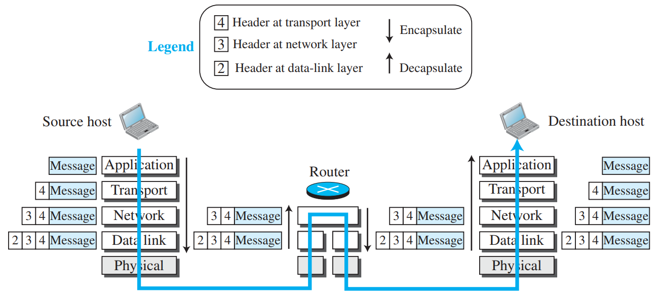
As user data moves down the protocol stack at the sender, each layer prepends a protocol header (and sometimes a trailer). This is called encapsulation. At the destination, each layer strips its header moving up the stack. This is called decapsulation.
Figure 2.7: Encapsulation at Host A, Router Hop Replacement, and Decapsulation at Host B (Page 9)
Crucial KTU Exam Point: When a packet passes through an intermediate router, the router decapsulates the data link frame up to the network layer, checks the destination IP address to choose the outgoing interface, and then re-encapsulates the datagram into a brand-new data link frame with new source and destination MAC addresses!
5. Addressing at Different Layers
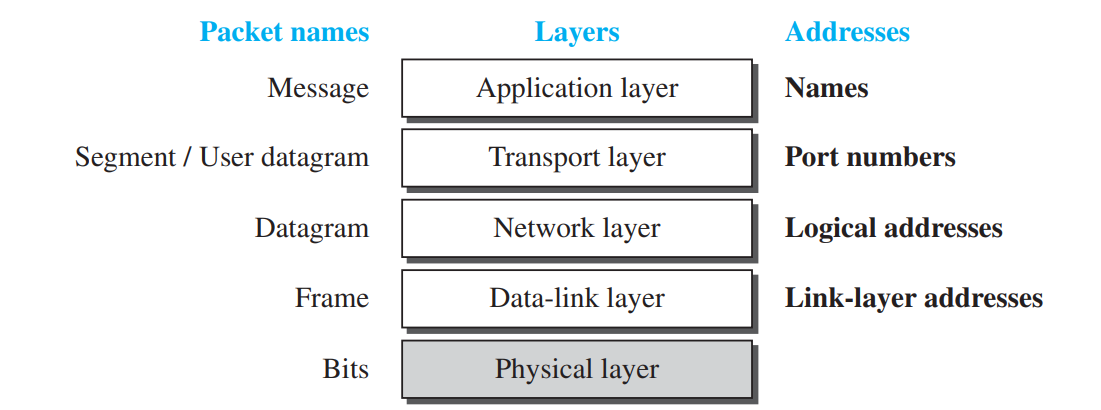
To successfully deliver data across the Internet, four levels of addresses are used:
Figure 2.8: Four Levels of Addresses in the TCP/IP Architecture (Page 10)
Layer
Address Type
Bit Size
Example
Scope & Purpose
Application
Specific Address
Variable text
user@example.com, www.ktu.edu.in
Human-friendly identifiers for services or users.
Transport
Port Address
16 bits (0 to 65535)
Port 80 (HTTP), Port 25 (SMTP)
Identifies the specific sending or receiving process on a host.
Network
Logical / IP Address
32 bits (IPv4) / 128 bits (IPv6)
192.168.1.1, 142.250.190.46
Globally identifies a host or interface across the entire Internet.
Data Link
Physical address / MAC Address
48 bits (6 bytes hex)
00:1A:2B:3C:4D:5E
Identifies the Network Interface Card (NIC) within a local network hop.
6. Multiplexing, Demultiplexing & OSI Comparison
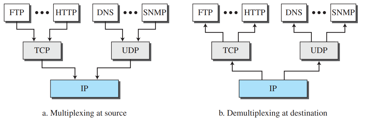
Multiplexing: At the sender, a lower-layer protocol (like IP) can encapsulate packets coming from multiple higher-layer protocols (TCP, UDP, ICMP) one at a time. Demultiplexing: At the receiver, a protocol decapsulates packets and delivers them to the correct higher-layer protocol based on protocol ID or port numbers.
Figure 2.9: Multiplexing at Sender and Demultiplexing at Receiver (Page 11)
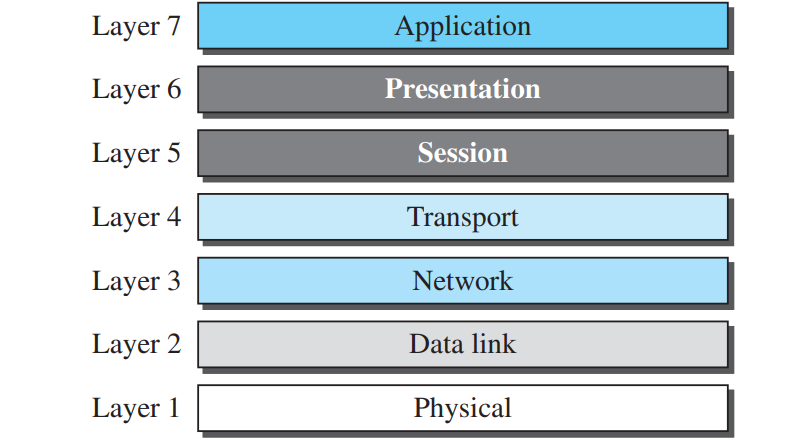
Figure 2.10: The ISO-OSI 7-Layer Reference Model (Page 11)
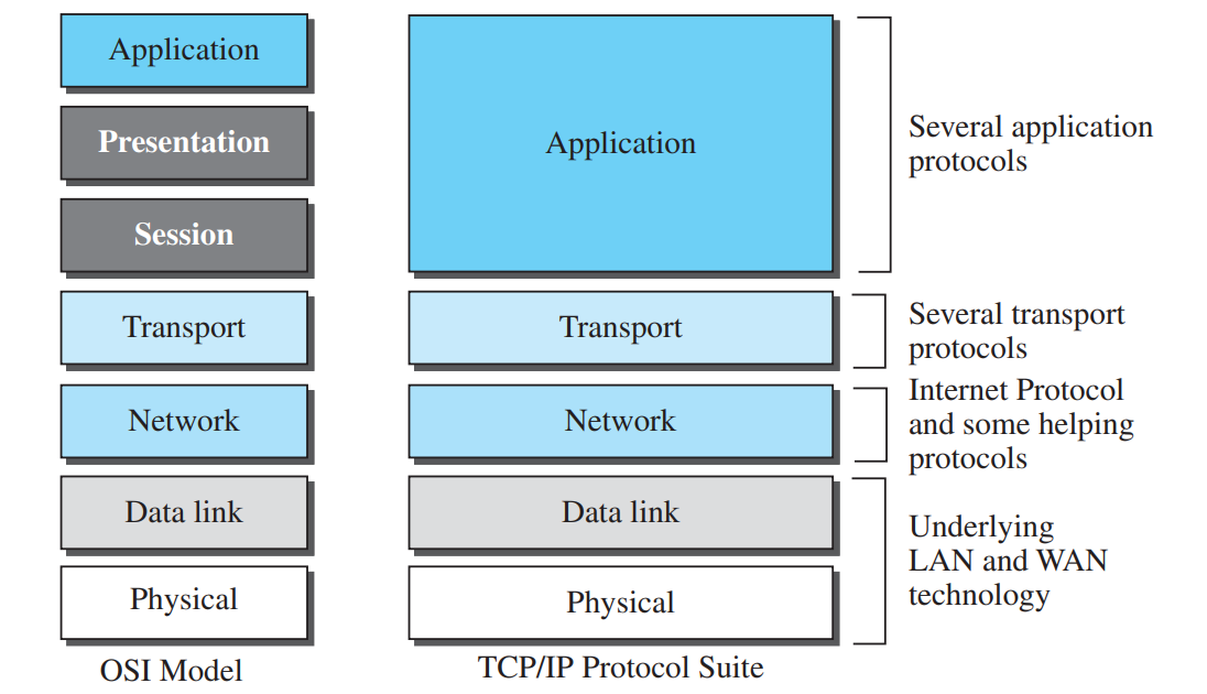
Figure 2.11: Direct Comparison: OSI 7-Layer vs. TCP/IP 5-Layer Model (Page 12)
Why TCP/IP merged Presentation & Session into Application: The designers of TCP/IP felt that presentation functions (encryption, compression, encoding) and session management (dialogue control, checkpoints) are best implemented inside individual application programs when needed, rather than adding two separate protocol layers that introduce processing overhead for every simple network transaction.
🏛️ The OSI 7-Layer Model: Functions of Session and Presentation Layers
The International Organization for Standardization (ISO) created the Open Systems Interconnection (OSI) 7-layer reference model. The two layers in OSI that are merged into the Application layer in TCP/IP are:
Presentation Layer (Layer 6): Concerned with the syntax and semantics of the information exchanged. Responsible for:
Translation: Converting character encodings between different computer systems (e.g., EBCDIC to ASCII).
Encryption & Decryption: Ensuring privacy and confidentiality of sensitive data during transit.
Compression: Reducing the number of bits in multimedia streams to optimize link bandwidth.
Session Layer (Layer 5): Establishes, manages, and terminates dialogues between communicating applications. Responsible for:
Dialog Control: Determines whether communication is half-duplex (two-way alternate) or full-duplex (two-way simultaneous).
Synchronization & Checkpointing: Inserts checkpoints into long data streams. If a 2-hour file transfer crashes at minute 50, the session layer allows retransmission to resume from the last valid checkpoint rather than restarting from the beginning.
⚠️ Why Did the OSI Model Fail in Practice? (Why OSI was Not Successful)
Although the OSI model is widely studied as a theoretical teaching reference, it never achieved widespread commercial deployment over TCP/IP due to three primary historical reasons:
Bad Timing: The OSI standards were finalized in the late 1970s and 1980s. It was completed when TCP/IP was fully in place; changing would cost too much. Organizations had already invested billions in TCP/IP infrastructure, and replacing it would cost too much.
Flawed Technology & Redundancy: Some layers (Session and Presentation) were never fully defined or needed separate software protocols, while functions like flow control, error checking, and addressing were needlessly duplicated across multiple layers (Transport and Data Link).
Poor Initial Implementations: Early software implementations of OSI protocols were complex, bulky, and noticeably slower compared to the lean, modular UNIX implementations of the TCP/IP stack.
📝 KTU Examination Essay Answer (9 Marks)
Question: Explain the layered architecture of the TCP/IP protocol suite with a neat diagram. State the function of each layer and the data unit handled at each layer. [KTU Part B High-Frequency]
Structure to secure full 9/9 marks:
Introduction (1 Mark): Define TCP/IP as a hierarchical 5-layer protocol suite developed before OSI, serving as the communication protocol for the Internet.
Neat Architecture Diagram (2 Marks): Draw the 5 layers vertically (Application, Transport, Network, Data Link, Physical) showing data flow and PDUs.
Layer Functions & PDUs (5 Marks - 1 mark per layer):
Data Link Layer (PDU: Frame): Hop-to-hop frame delivery, physical MAC addressing, error detection.
Physical Layer (PDU: Bits): Bit transmission over physical media, signal encoding, hardware connectors.
Addressing Scheme Summary (1 Mark): State the 4 addressing levels (Specific, Port, Logical, Physical address).
PART 03CORE THEORY • 3M / 5M
Application-Layer Paradigms & Socket Concept
PDF Pages: 13 – 16
💡 What is the Application Layer?
The Application Layer is the top layer in the TCP/IP suite. It is the only layer that directly interacts with the end-user. All four lower layers (Transport, Network, Data Link, Physical) exist solely to provide end-to-end communication services to the Application Layer.
1. Client-Server Paradigm vs. Peer-to-Peer Paradigm
Modern network applications are built following two major architectural paradigms:
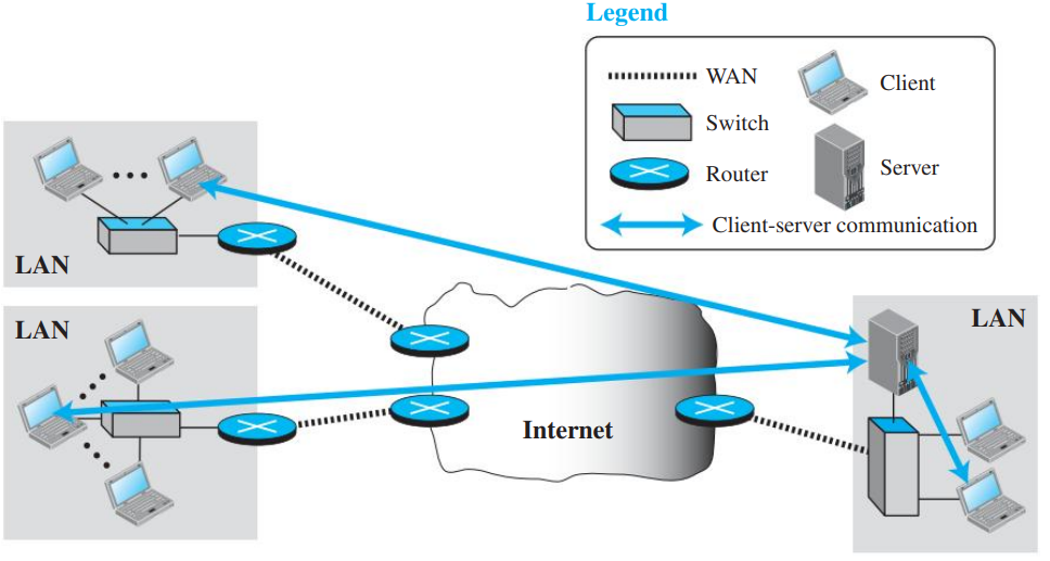
Figure 3.1: The Traditional Client-Server Paradigm (Page 13)
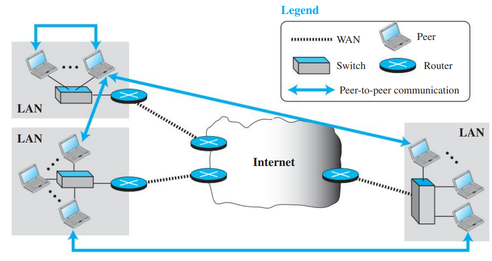
Figure 3.2: The Peer-to-Peer (P2P) Paradigm (Page 14)
Feature
Client-Server Paradigm
Peer-to-Peer (P2P) Paradigm
Architecture
Centralized. Clear distinction between service requester (client) and service provider (server).
Decentralized. Nodes (peers) have equal capabilities and responsibilities.
Server Uptime
Server must run continuously (24/7) with a fixed, well-known IP address.
No central server runs all the time; peers join and leave dynamically (churn).
Role of Nodes
Client only requests service; Server only provides service.
A peer can provide service at one moment and receive service at another, or do both simultaneously.
Scalability
Bottleneck at high loads; scaling requires massive data centers and load balancers.
Self-scaling: as new peers arrive to download, they also bring upload bandwidth capacity.
Single Point of Failure
Yes. If the central server crashes, the entire service becomes unavailable.
No single point of failure; resilient to individual peer failures.
Examples
World Wide Web (HTTP), Email (SMTP/POP3), FTP, DNS.
BitTorrent, Gnutella, Blockchain (Bitcoin), VoIP (early Skype).
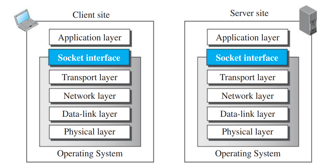
How does an application program written by a software developer communicate with the operating system's networking stack? It uses an Application Programming Interface (API).
The standard API used across modern operating systems is the Socket Interface (first introduced in Berkeley UNIX / BSD Sockets).
Figure 3.3: Socket Interface Between Application Layer and OS Transport Layer (Page 15)
🔑 What is a Socket?
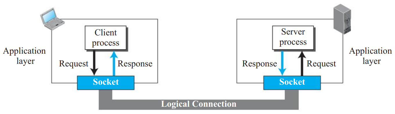
A socket is a software abstraction that acts as a door or endpoint for communication between a user application process and the network protocol stack. To send data, the process pushes bytes through its socket door; to receive data, it reads bytes from the socket door.
Figure 3.4: Sockets Used by Client and Server Processes (Page 15)
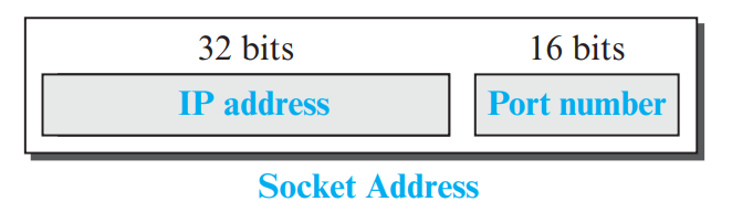
Figure 3.5: Composition of a Socket Address (Page 15)
Example:200.100.10.5:80 specifies that the packet is directed to the host at IP 200.100.10.5 and specifically to the Web Server process listening on Port 80.
3. Finding Socket Addresses (PDF Page 16)
For communication to occur, both the client process and the server process must obtain local and remote socket addresses:
Site
Address Role
How It Is Obtained
Server
Local Socket Address
The IP address is assigned to the server's network interface by the OS. Standard servers listen on well-known ports (e.g., HTTP = 80, SMTP = 25); other servers get a port designated by the system architect.
Server
Remote Socket Address
Extracted dynamically from the incoming client request packet headers (source IP and source port). It changes with each connecting client.
Client
Local Socket Address
The OS provides the local IP address. The port is a temporary, dynamically assigned ephemeral port number (range 49152–65535) unused by any other active client.
Client
Remote Socket Address
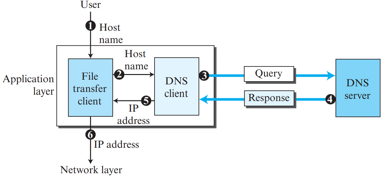
The server's port number is well known (e.g., 80). The server's IP address is resolved from its domain name using a DNS lookup.
PART 04VERY HIGH PRIORITY • 3M / 6M / 9M
World Wide Web (WWW) and HTTP Protocol
PDF Pages: 17 – 23
💡 What is the World Wide Web & HTTP?
The World Wide Web (WWW) is a distributed client-server information service. Web pages distributed across millions of servers worldwide contain text, images, multimedia, and hyperlinks. HTTP (Hypertext Transfer Protocol) is the underlying application-layer protocol that powers the Web.
1. Web Architecture & Uniform Resource Locator (URL)
A Web client (browser) requests Web documents from a Web server using HTTP over a reliable TCP transport connection (default port 80). Each resource on the Web is uniquely addressed by a Uniform Resource Locator (URL):
Figure 4.1: Distributed Web Client-Server Architecture (Page 17)
Protocol: The application-layer client-server protocol used (e.g., http, https, ftp).
Host: The domain name or IP address of the server holding the resource (e.g., www.mhhe.com).
Port (optional): The TCP port number where the server process is listening (default 80 for HTTP, 443 for HTTPS).
Path: The local file-path directory on the server identifying the specific file (e.g., /compsci/forouzan/chapter1.html).
2. Non-Persistent vs. Persistent HTTP Connections
HTTP operates over TCP. An HTML base document often references multiple embedded objects (e.g., 10 images). How these objects are fetched differentiates the two connection strategies:
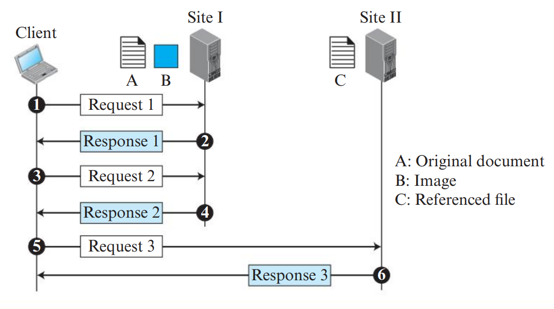
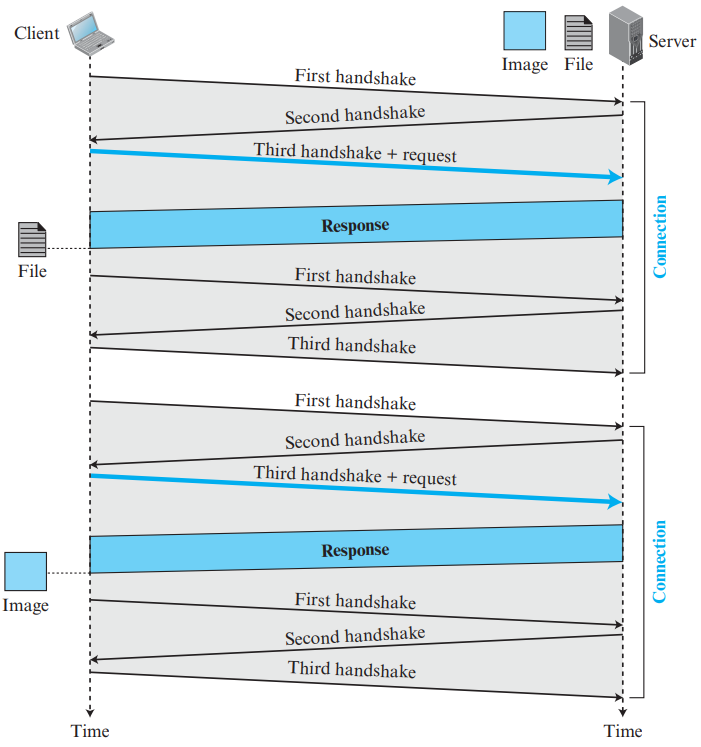
Figure 4.4: Non-Persistent HTTP: Separate TCP Connection Per Object (Page 19)
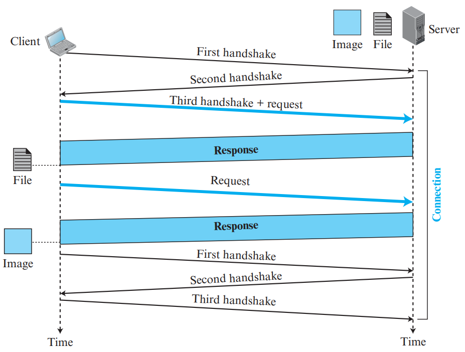
Figure 4.5: Persistent HTTP: Single TCP Connection for All Objects (Page 19)
Comparison Parameter
Non-Persistent HTTP (HTTP/1.0)
Persistent HTTP (HTTP/1.1)
TCP Connections
A separate new TCP connection is opened and closed for every single object requested.
A single TCP connection is kept open for the base HTML and all embedded objects.
Connection Overhead
High server overhead; server must allocate buffers and TCP variables for each connection.
Low server overhead; single TCP state maintained per client session.
Round-Trip Time (RTT) per Object
Requires 2 RTTs per object (1 RTT for TCP 3-way handshake + 1 RTT for HTTP request/data).
Without pipelining: 1 RTT per object after initial setup. With pipelining: all objects requested back-to-back in ~1 RTT total!
Default in Protocols
Default in HTTP/1.0.
Default in HTTP/1.1 (header: Connection: keep-alive).
Suppose a base HTML file contains references to \(N\) embedded images. Let \(\text{RTT}\) be the Round Trip Time between client and server, and assume object transmission time is negligible.
Non-Persistent HTTP Total Time:
Base HTML requires \(2 \times \text{RTT}\). Each of the \(N\) images requires \(2 \times \text{RTT}\).
\[T_{\text{non-persistent}} = 2 \times \text{RTT} + 2N \times \text{RTT} = 2(N + 1)\,\text{RTT}\]
Persistent HTTP (Without Pipelining):
Base HTML setup + fetch takes \(2 \times \text{RTT}\). Each image is requested sequentially over the open connection taking \(1 \times \text{RTT}\) each.
\[T_{\text{persistent, no-pipe}} = 2 \times \text{RTT} + N \times \text{RTT} = (N + 2)\,\text{RTT}\]
Persistent HTTP (With Pipelining):
Base HTML takes \(2 \times \text{RTT}\). All \(N\) images are sent in one pipelined burst taking \(1 \times \text{RTT}\).
\[T_{\text{persistent, pipe}} = 2 \times \text{RTT} + 1 \times \text{RTT} = 3\,\text{RTT}\]
Example: For \(N = 10\) images, Non-Persistent takes \(22\,\text{RTT}\), Persistent without pipelining takes \(12\,\text{RTT}\), and Persistent with pipelining takes only \(3\,\text{RTT}\)!
3. HTTP Message Formats & Methods
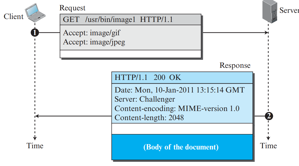
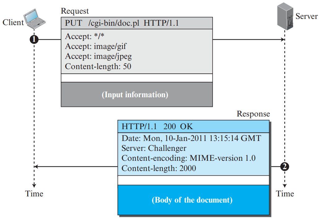
📜 HTTP Message Structure: Request Line and Status Line
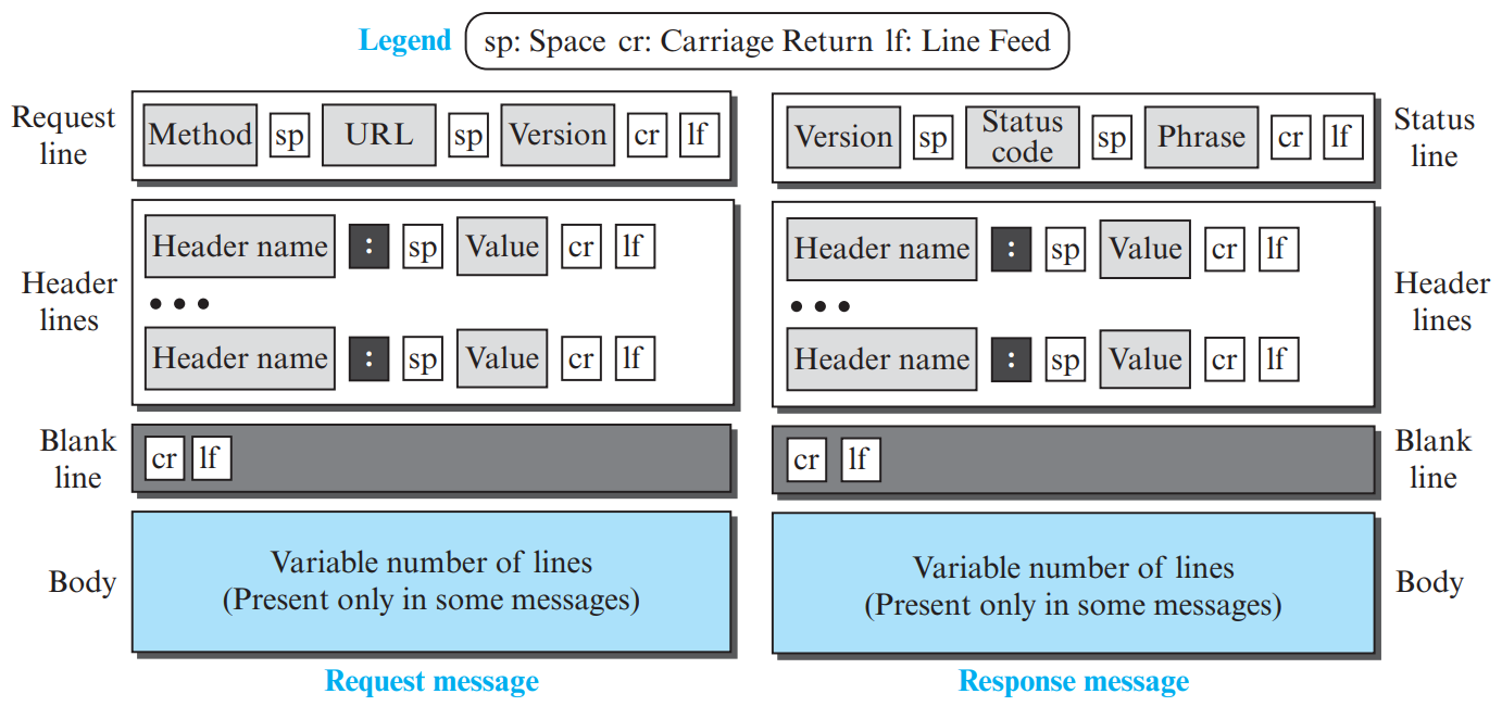
Both HTTP Request and HTTP Response messages follow a standardized 4-part structure:
HTTP Request Message
Request Line: Contains three fields separated by spaces:
Method URL HTTP-Version (e.g., GET /index.html HTTP/1.1).
Blank Line: A carriage-return and line-feed (\r\n) marking the end of headers.
Entity Body (Optional): Contains form input or payload data (used in POST and PUT).
HTTP Response Message
Status Line: Contains three fields:
HTTP-Version Status-Code Status-Phrase (e.g., HTTP/1.1 200 OK).
Header Lines: Server metadata (e.g., Date: Sun, 22 Nov 2026, Server: Apache, Set-Cookie: session=xyz, Content-Length: 2048).
Blank Line: A mandatory \r\n separating headers from body.
Entity Body: The actual requested file or web content (HTML document, JPEG image).
HTTP is an ASCII-text based protocol. There are two kinds of messages: Request Messages and Response Messages.
Figure 4.6: HTTP Request Message Format (Page 21)
Figure 4.7: HTTP Response Message Format (Page 21)
HTTP Request Methods (PDF Page 20)
Method
Action Performed
Safe / Idempotent
GET
Requests a document from the server. Carries no entity body.
Safe & Idempotent
POST
Sends user input/data (e.g., form data) in the body to be processed by server.
Not Idempotent
HEAD
Requests only the header lines of the response without the entity body. (Used for testing/caching).
Safe & Idempotent
PUT
Uploads a replacement document to the server at the specified URL.
Idempotent
DELETE
Requests the deletion of the specified document from the server.
Idempotent
OPTIONS
Inquires about available options and supported methods.
Safe & Idempotent
TRACE
Echoes back the received request for network path diagnostics.
Safe & Idempotent
CONNECT
Reserved for SSL/TLS tunneling through proxy servers.
Special
Comprehensive HTTP Request Headers (PDF Page 20)
Request Header
Standard Meaning & Usage
User-agent
Identifies the client software / browser program.
Accept
Specifies the media/MIME formats the client can accept (e.g., text/html).
Accept-charset
Specifies the character sets accepted by client (e.g., UTF-8).
Accept-encoding
Specifies the compression schemes accepted (e.g., gzip, deflate).
Accept-language
Preferred natural language (e.g., en-US).
Authorization
Carries credentials for authenticating client with server.
Host
Host and port of the requested resource (mandatory in HTTP/1.1 for virtual hosting).
Date
Current date and time of request generation.
Upgrade
Requests switching to a newer or preferred protocol (e.g., HTTP/2, WebSocket).
Cookie
Returns a previously stored cookie to the server.
If-Modified-Since
Used for conditional caching; requests document only if modified since date.
HTTP Status Codes (Response Message)
Code Range
Category
Crucial KTU Exam Examples
1xx
Informational
100 Continue (Server received request headers, client can proceed).
2xx
Successful
200 OK (Request succeeded; document follows in entity body).
3xx
Redirection
301 Moved Permanently; 304 Not Modified (Cached copy is fresh!).
4xx
Client Error
400 Bad Request; 404 Not Found (Document does not exist).
5xx
Server Error
500 Internal Server Error; 503 Service Unavailable; 505 HTTP Version Not Supported (Overloaded).
4. Maintaining State: HTTP Cookies
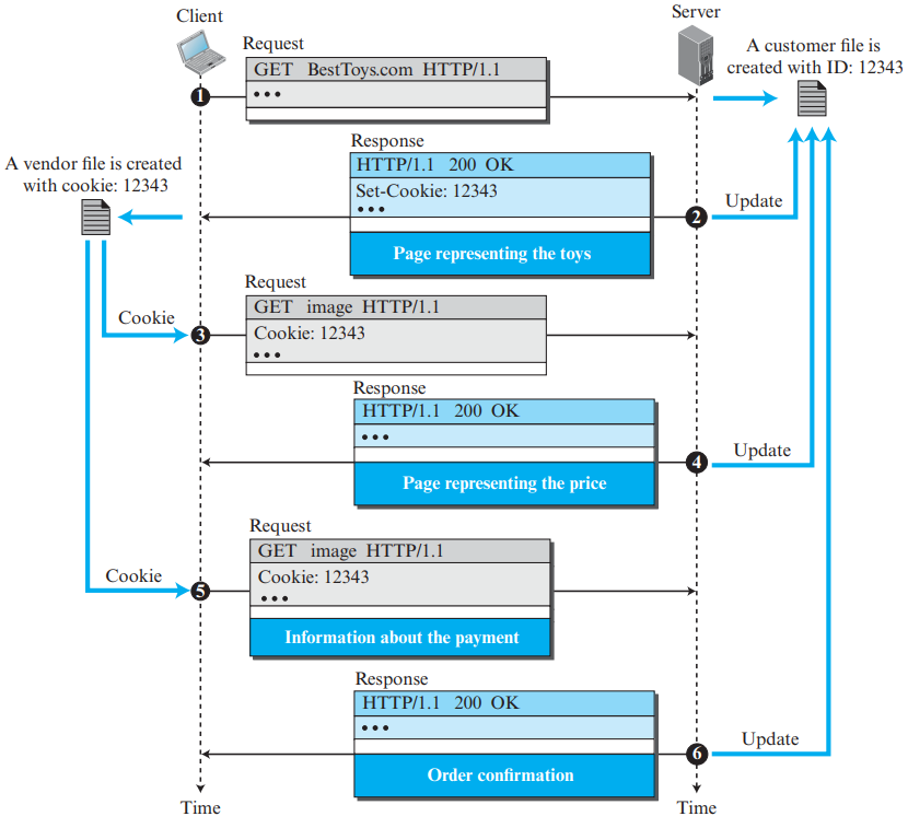
HTTP is fundamentally a stateless protocol: the server does not retain information about earlier requests from the same client. To maintain state (e.g., shopping carts, login authentication, user preferences), Cookies are employed.
Figure 4.8: Cookie Creation, Storage, and Tracking Across Sessions (Page 22)
4-Step Cookie Workflow:
Client sends an initial HTTP request to the server without a cookie.
Server generates a unique cookie ID, stores it in its database, and replies with header: Set-Cookie: 123456.
Browser stores the cookie in its local cookie file indexed by server domain.
On all subsequent visits to that server, browser includes header: Cookie: 123456, allowing server to identify the user.
5. Web Caching & Proxy Servers
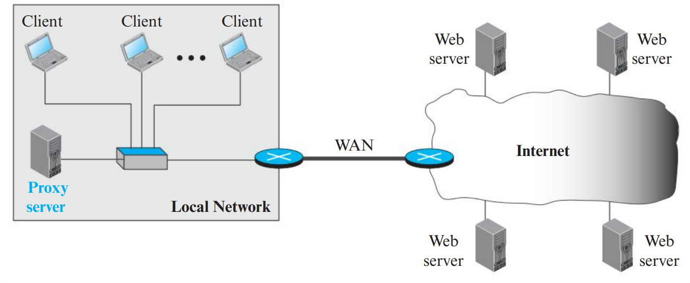
A Proxy Server (Web Cache) is a network entity that satisfies HTTP requests on behalf of an origin Web server. It stores recent request-response pairs in local storage to reduce access latency, conserve enterprise bandwidth, and alleviate origin server load.
Figure 4.9: Proxy Server Intercepting Client Requests (Page 23)
Figure 4.10: Conditional GET with 304 Not Modified Response (Page 23)
⭐ Conditional GET: How Caches Keep Content Fresh
A proxy cache must verify that its cached copy has not become stale. It sends a Conditional GET request to the origin server containing the header:
If-Modified-Since: Wed, 21 Oct 2026 07:28:00 GMT
If NOT modified: Origin server returns 304 Not Modified with NO message body. Saves massive bandwidth!
If modified: Origin server sends 200 OK along with the updated document in the entity body.
PART 05EXAM FAVORITE • 3M / 5M
File Transfer Protocol (FTP)
PDF Pages: 24 – 26
💡 Why is FTP Different from HTTP?
FTP is the standard client-server protocol used for transferring files between hosts. Unlike HTTP, which sends commands and files over the same connection, FTP establishes two separate connections between the client and server.
1. The Dual-Connection Architecture of FTP
FTP separates control commands from data transmission by using two distinct TCP connections:
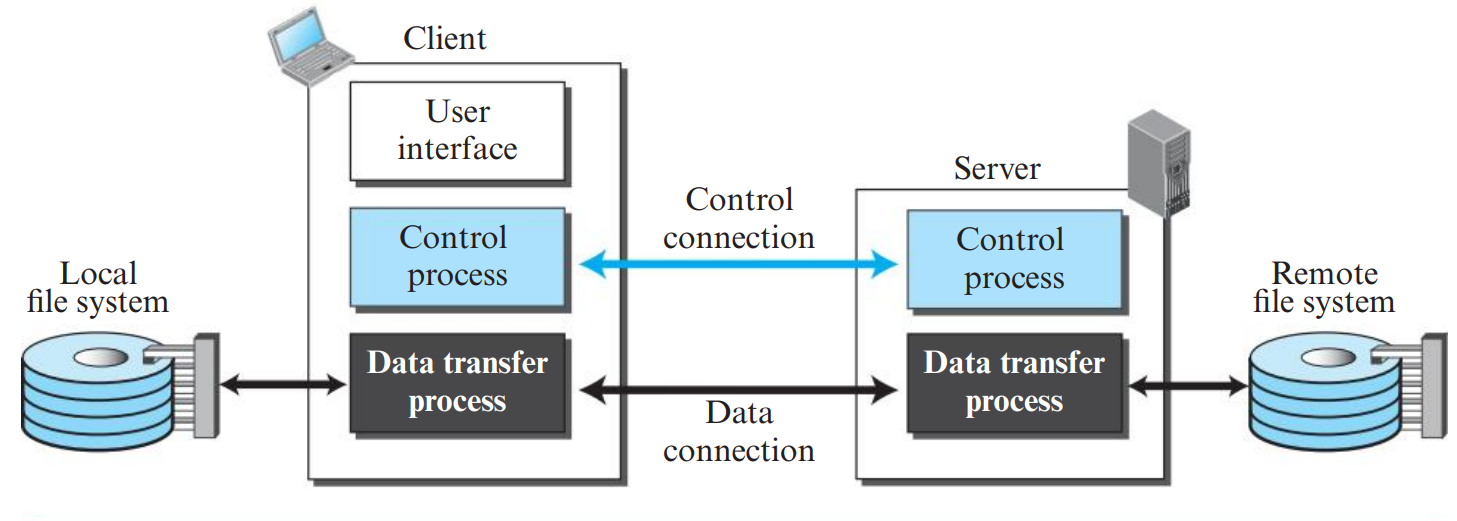
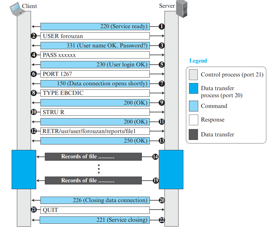
Control Connection (Port 21): Used for transmitting user credentials, commands (e.g., USER, PASS, RETR), and server reply codes. It remains open for the entire duration of the user's interactive FTP session.
Data Connection (Port 20): Used strictly for transmitting the actual file contents or directory listings. It is created dynamically on-demand for every individual file transfer and is closed immediately once that transfer finishes.
Figure 5.1: FTP Architecture: Control Connection (21) and Data Connection (20) (Page 26)
Exam Drawing Requirement: Clearly draw the Client side with 3 boxes (User Interface, Control Process, Data Transfer Process) and the Server side with 2 boxes (Control Process, Data Transfer Process). Connect the two Control Processes with a line labeled Control Connection (Port 21) and the two Data Transfer Processes with a line labeled Data Connection (Port 20).
⭐ Out-of-Band Control vs. In-Band Control (KTU 3-Mark Question)
Because FTP sends its control information (commands and replies) over a separate TCP connection from the data, FTP is said to send its control information out-of-band.
In contrast, protocols like HTTP and SMTP send their request headers and data over the exact same TCP connection; therefore, HTTP and SMTP use in-band control.
2. Active Mode vs. Passive Mode in FTP
🔌 Active Mode vs. Passive Mode: The PORT and PASV Commands
Because firewalls and NAT routers block unsolicited incoming connections, FTP supports two distinct operating modes:
Active Mode (PORT command):
Client initiates control connection to server port 21 from ephemeral port \(C\).
When a file transfer is required, client opens a listening ephemeral port \(D\) and transmits its IP and port to the server using the PORT command (e.g., PORT 192,168,1,5,19,136 where port = \(19 \times 256 + 136 = 5000\)).
The server initiates an active open from its standard port 20 to the client's port \(D\). (Often blocked by client-side firewalls!)
Passive Mode (PASV command):
Client sends the PASV command to the server over the control connection.
Server opens a dynamic ephemeral port \(S\) and replies with its IP address and port number.
The client initiates the data connection from its own ephemeral port to the server's port \(S\). This resolves firewall issues because the client initiates both connections.
Parameter
Active Mode (Default)
Passive Mode (PASV)
Who Initiates Data Conn?
The Server initiates the connection to the client.
The Client initiates the connection to the server.
Command Sent
Client sends PORT h1,h2,h3,h4,p1,p2 telling server its IP and port.
Client sends PASV; server replies with its listening IP and port.
Firewall Friendliness
Poor. Client firewalls frequently block incoming server connections.
3xx: Positive Intermediate reply (Command accepted, but further info needed, e.g., password).
4xx: Transient Negative Completion reply (Temporary failure; command may be retried).
5xx: Permanent Negative Completion reply (Fatal error; command not accepted).
Reply Code
Description
Reply Code
Description
125
Data connection already open; transfer starting.
250
Requested file action okay, completed.
150
File status okay; about to open data connection.
331
User name okay, password needed.
200
Command okay.
425
Can't open data connection.
220
Service ready for new user.
530
Not logged in.
221
Service closing control connection (Logged out).
550
Requested action not taken; file unavailable.
226
Closing data connection; requested file action successful.
500
Syntax error; command unrecognized.
PART 06VERY HIGH PRIORITY • 5M / 9M ESSAY
Electronic Mail (E-mail) Architecture & MIME
PDF Pages: 27 – 35
💡 Why is E-mail Architecture Asynchronous?
Unlike HTTP or FTP where both parties are connected live, e-mail is an asynchronous store-and-forward system. The sender can send an e-mail when the receiver is offline. The message waits in intermediate mail servers until the recipient chooses to log in and retrieve it.
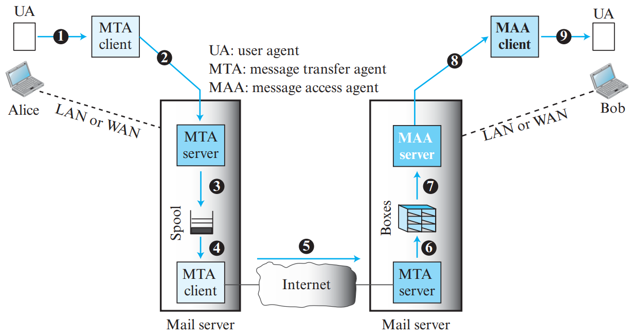
1. Email Architecture: The Three Core Components
An e-mail system is composed of three distinct functional agents:
User Agent (UA): Software program that lets the user read, compose, reply to, and forward e-mails (e.g., Thunderbird, Outlook, Apple Mail).
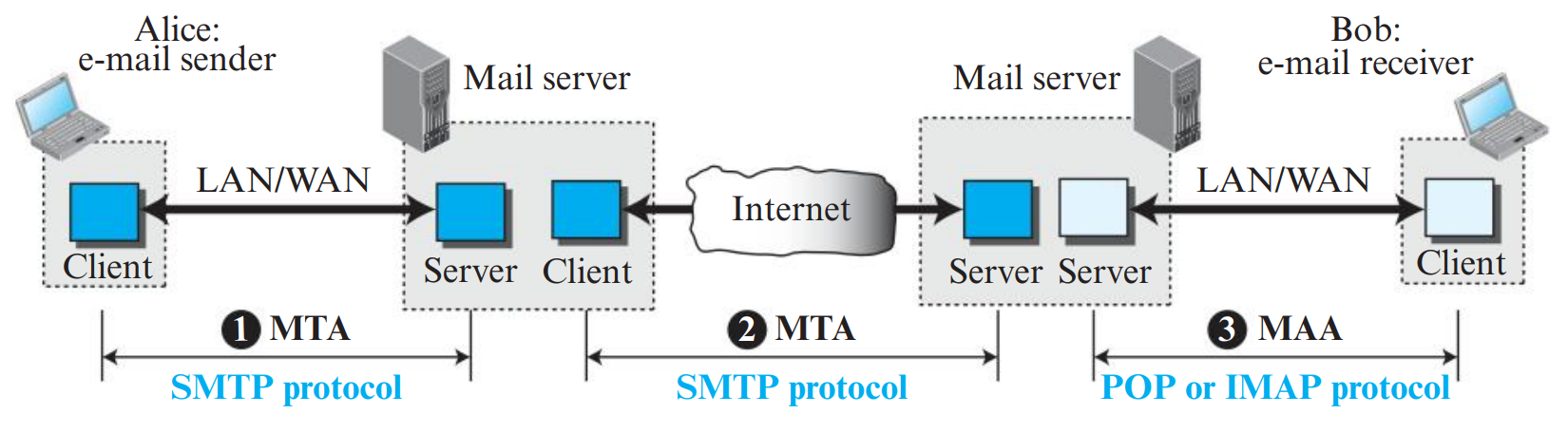
Message Transfer Agent (MTA): Server-side software that pushes e-mails from sender's mail server to recipient's mail server using SMTP (Simple Mail Transfer Protocol).
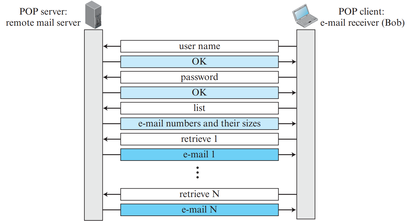
Message Access Agent (MAA): Protocol used by the recipient to pull e-mails from their mailbox on the mail server to their local machine (using POP3 or IMAP4).
Figure 6.1: Complete E-mail Architecture: Alice to Bob (Page 27)
⭐ Crucial KTU Distinction: Push vs. Pull Protocols
SMTP is a PUSH Protocol: The client sends (pushes) the message to the server. POP3 and IMAP4 are PULL Protocols: The client retrieves (pulls) the message from the server mailbox.
2. SMTP (Simple Mail Transfer Protocol)
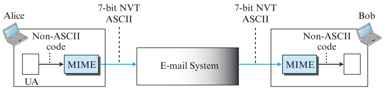
SMTP is the standard protocol for transferring mail reliably over TCP (port 25). It uses 7-bit NVT ASCII text format.
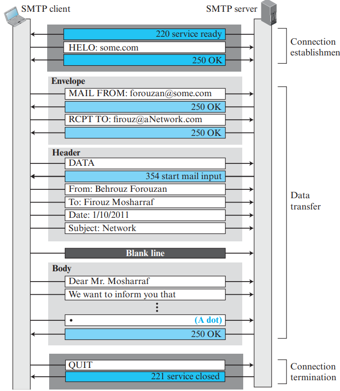
Figure 6.3: The Three Phases of an SMTP Session (Page 30)
Comprehensive SMTP Commands (PDF Page 29)
Keyword
Argument
Description
HELO / EHLO
Sender's host domain
Identifies client to server (EHLO for Extended SMTP).
MAIL FROM
Sender email address
Identifies message author and sender mailbox.
RCPT TO
Recipient email address
Identifies intended recipient; repeated for multiple recipients.
DATA
None
Initiates mail body input; terminated by line with single dot (<CRLF>.<CRLF>).
RSET
None
Resets/aborts current mail transaction without closing connection.
VRFY
User / email name
Verifies recipient address without sending mail.
NOOP
None
No operation; checks if connection is alive.
TURN
None
Reverses roles of client and server.
EXPN
Mailing list name
Expands mailing list membership.
HELP
Command name
Requests documentation on specific command.
QUIT
None
Terminates SMTP session and closes connection.
The Three Phases of SMTP:
Connection Establishment: Client connects to server port 25. Server responds with 220 Service Ready. Client introduces itself: HELO client.domain.com. Server replies 250 OK.
Mail Transfer: Sender issues MAIL FROM: <alice@domain.com>. Server replies 250 OK. Sender issues RCPT TO: <bob@domain.com>. Server replies 250 OK. Sender issues DATA. Server replies 354 Start mail input; end with <CRLF>.<CRLF>. Client transmits headers, blank line, body text, and ends with a single period . on a line by itself. Server: 250 OK.
Connection Termination: Client issues QUIT. Server replies 221 Service closing transmission channel.
3. Mail Access Protocols: POP3 vs. IMAP4
📥 POP3 Operating Modes: Download-and-Delete vs. Download-and-Keep
Post Office Protocol version 3 (POP3) operates in two distinct user modes:
Download-and-Delete Mode (Download and delete): The client downloads all messages from the mail server to the local computer and deletes them from the server mailbox.
Disadvantage: The user cannot read or access their emails from another device (e.g., office computer or mobile phone).
Download-and-Keep Mode (Download and keep): The client downloads copies of messages while leaving the originals on the server.
Disadvantage: Status changes (marking an email as read, moving to folders, or deleting) are NOT synchronized across devices. Every new device downloads all messages again as unread.
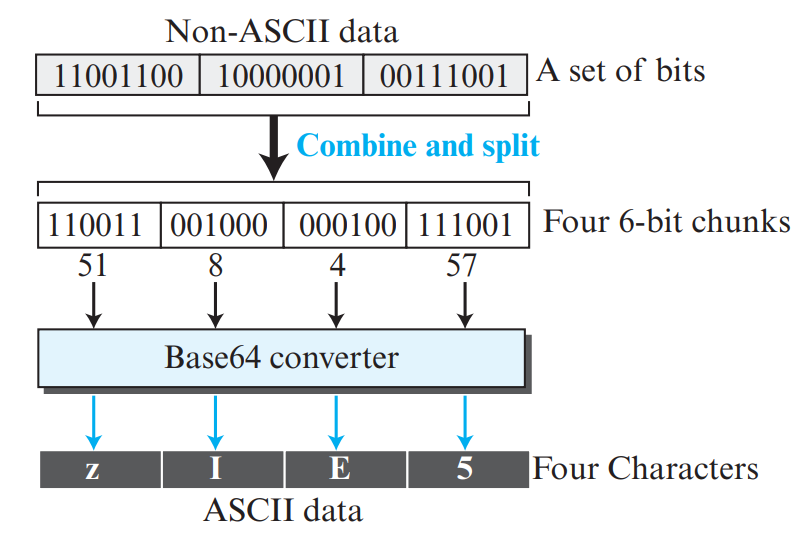
Base64 Mechanism: Takes 3 bytes of binary data (24 bits), divides them into four 6-bit chunks, and maps each 6-bit value (\(0 \text{ to } 63\)) to one of 64 printable ASCII characters (A–Z, a–z, 0–9, +, /). If input bytes are not a multiple of 3, padding character = is appended.
Overhead Formula: For \(B\) bytes of binary input, the encoded size is:
\[\text{Size}_{\text{Base64}} = \lceil \frac{B}{3} \rceil \times 4 \text{ bytes}\]
Data Overhead: Base64 incurs an overhead of:
\[\frac{4 - 3}{3} \times 100\% = 33.33\% \text{ size increase.}\]
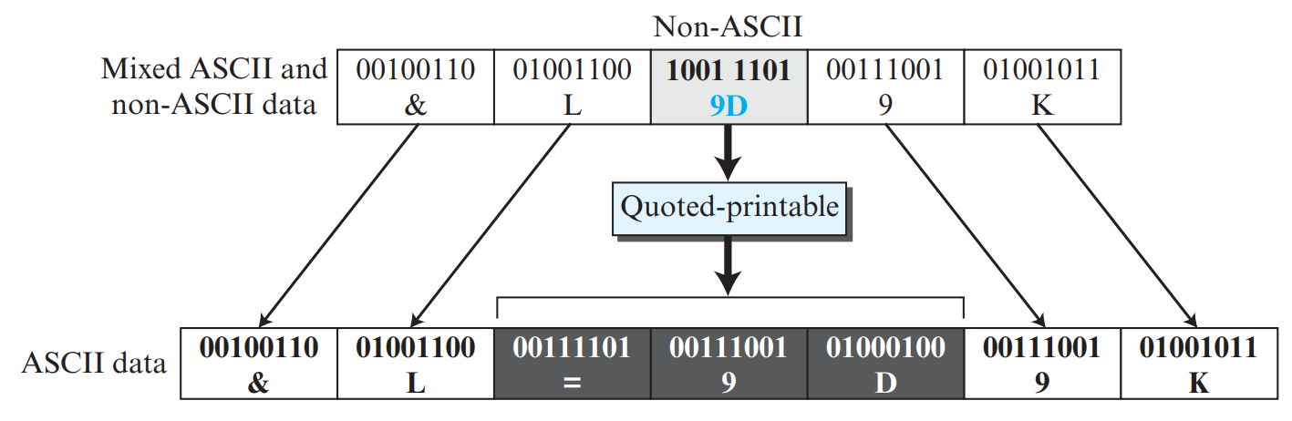
Quoted-Printable Encoding (Figure 6.8 from Notes)
Best for data that is mostly ASCII text with only a few non-ASCII special characters:
All printable standard ASCII characters are transmitted unmodified (1 byte).
Any non-ASCII byte (MSB = 1) is converted into three ASCII characters: an equals sign = followed by its 2-digit hexadecimal representation.
Example from PDF: The sequence 01001100 ('L'), 10011101 (hex 9D), and 00111001 ('9') is sent as L=9D9.
Figure 6.9: E-mail Security Using PGP or S/MIME (Page 35)
PART 07VERY HIGH PRIORITY • 3M / 6M / 9M
Domain Name System (DNS)
PDF Pages: 36 – 42
💡 Why DNS is Essential
Humans prefer mnemonic domain names like www.google.com or www.ktu.edu.in, but network routers require numerical IP addresses like 142.250.190.46. The Domain Name System (DNS) is the Internet's globally distributed, hierarchical directory service that maps domain names to IP addresses.
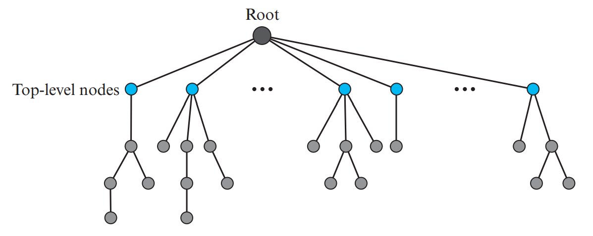
1. Flat vs. Hierarchical Name Space & The DNS Tree
Parameter
Flat Name Space
Hierarchical Name Space (DNS)
Structure
Sequence of characters with no internal structure or hierarchy.
Divided into structured parts (labels) separated by dots.
Management
Must be centralized to avoid duplicate names worldwide.
Decentralized; authority is delegated to separate entities.
Scalability
Cannot scale to large networks (like the Internet).
Extremely scalable; billions of unique names managed efficiently.
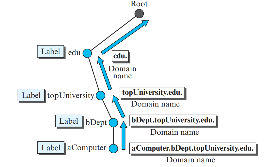
Figure 7.1: The Inverted Tree Hierarchy of Domain Name Space (Page 36)
Figure 7.2: Construction of a Domain Name from Labels (Page 36)
⭐ FQDN vs. PQDN (KTU 3-Mark Question)
Fully Qualified Domain Name (FQDN): A complete domain name that terminates with a null label (a trailing dot .). It uniquely identifies a node from the root down. Example:challenger.atc.fhda.edu.
Partially Qualified Domain Name (PQDN): An incomplete domain name that does not end with a trailing dot. The local DNS resolver automatically appends the local default domain suffix to complete it. Example:challenger (in the fhda.edu department).
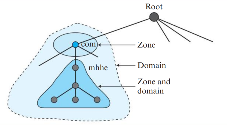
2. Domain vs. Zone & Name Server Hierarchy
A crucial distinction frequently asked in university exams:
Concept
Definition
Control & Responsibility
Domain
The entire subtree rooted at a particular node in the DNS tree.
Represents the complete conceptual naming branch, including all sub-domains.
Zone
The contiguous portion of the domain that a specific DNS server directly controls.
If a server delegates administration of a sub-domain to another server, that sub-domain leaves its zone!
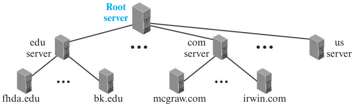
Figure 7.3: Hierarchy of DNS Servers (Root, Top-level domain [TLD], Authoritative) (Page 37)
Figure 7.4: Comparison Between a Domain and a Zone (Page 38)
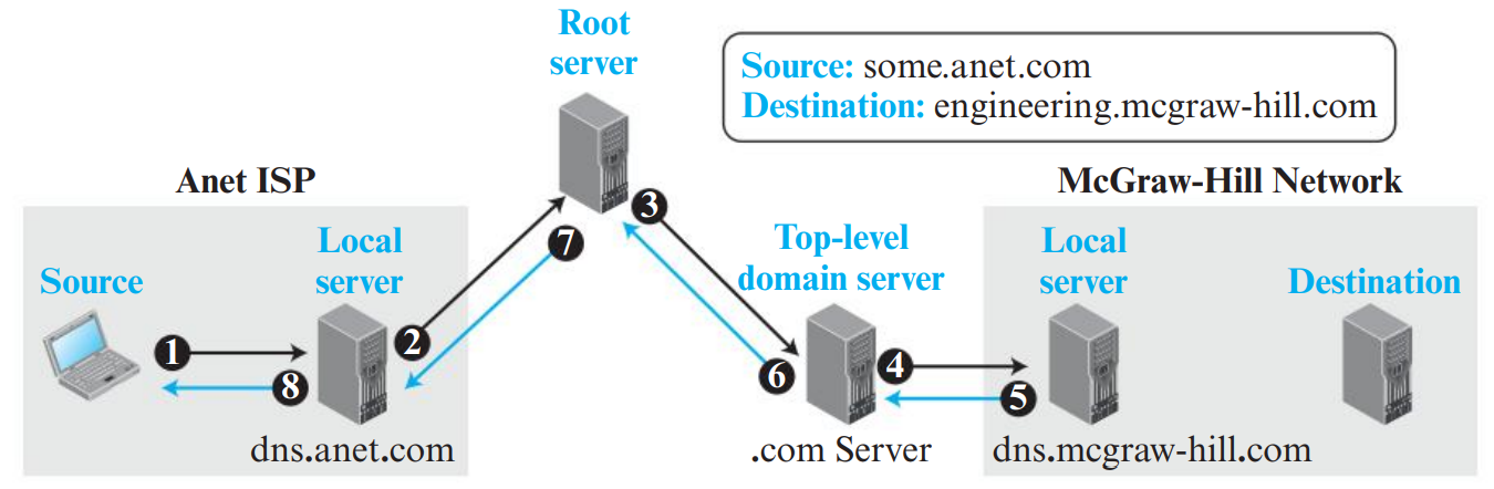
3. Name-Address Resolution: Recursive vs. Iterative
When a client program needs an IP address, its local stub resolver queries a DNS server using one of two resolution mechanisms:
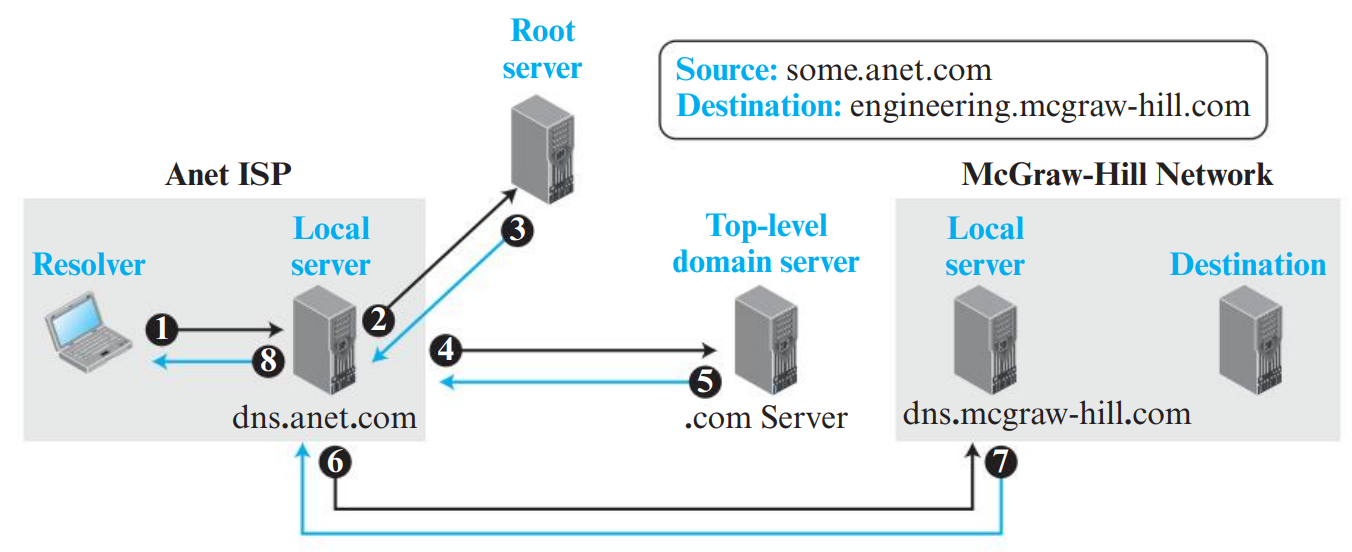
Figure 7.5: Recursive DNS Resolution (Page 39)
Figure 7.6: Iterative DNS Resolution (Page 39)
Parameter
Recursive Resolution
Iterative Resolution
Who Contacts Next Server?
The queried DNS server itself queries the next server on behalf of the client.
The server replies with a referral (IP of next server), and the requester contacts it directly.
Workload on Server
Heavy workload on intermediate and root servers.
Light workload on root and TLD servers.
Where It Is Used
Between client host and Local DNS Server.
Between Local DNS Server and Root / TLD / Authoritative servers.
4. DNS Message Format & Resource Records (RR)
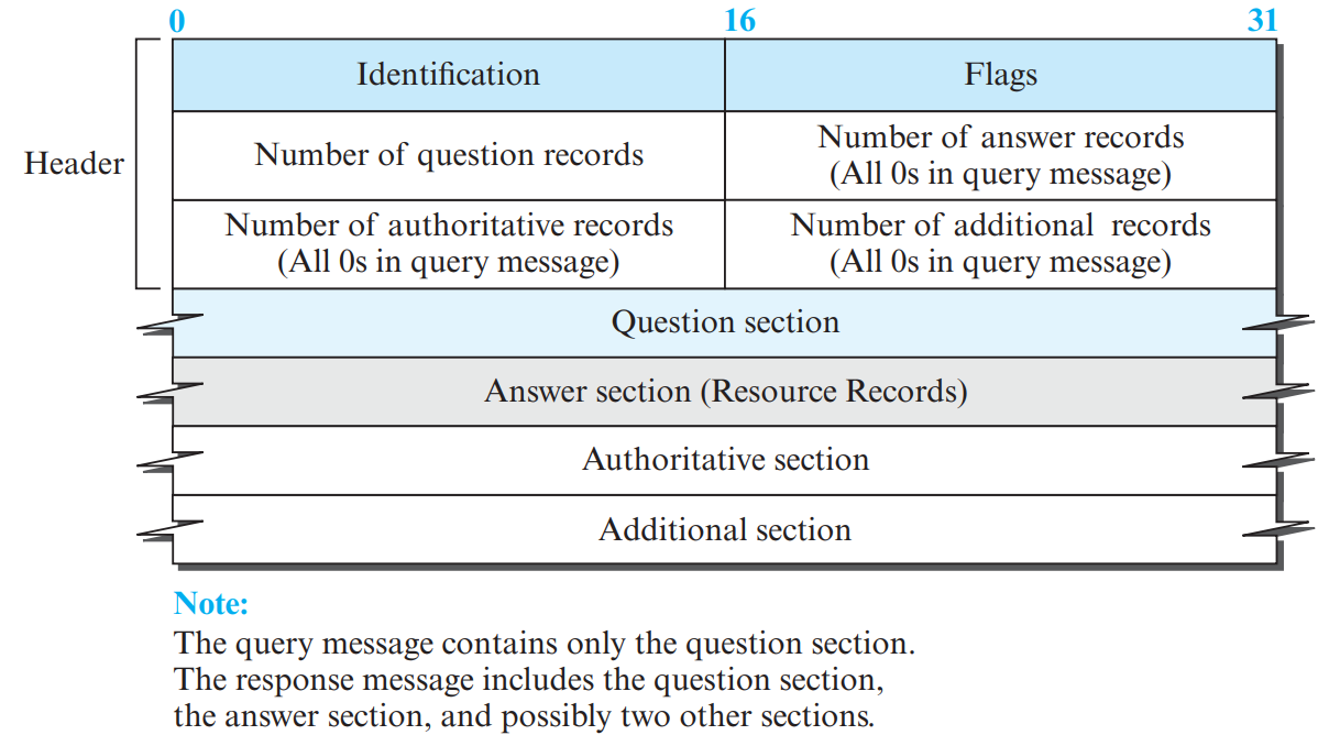
Figure 7.7: DNS Query/Response Message Format (Page 41)
DNS Message Structure: A fixed 12-byte Header (Identification, Flags, Counts) followed by 4 variable-length sections: Question, Answer, Authoritative, and Additional records.
Common DNS Resource Record (RR) Types
Type
Meaning
Value Stored
Example Usage
A (Type A)
IPv4 Address
32-bit IPv4 address (Type A)
example.com -> 93.184.216.34
AAAA (Type AAAA)
IPv6 Address
128-bit IPv6 address (Type AAAA quad-A)
example.com -> 2606:2800:220:1::
CNAME (Type CNAME)
Canonical Name
True primary domain name (Type CNAME alias)
www.example.com -> server1.example.com
NS (Type NS)
Name Server
Host name of authoritative DNS server (Type NS)
example.com -> ns1.example.com
MX (Type MX)
Mail Exchange
Host name of mail server + priority (Type MX)
example.com -> mail.example.com (Priority 10)
PTR (Type PTR)
Pointer
Domain name for Reverse DNS (Type PTR)
34.216.184.93.in-addr.arpa -> example.com
SOA (Type SOA)
Start of Authority
Authoritative zone parameters (SOA record)
serial number, refresh, retry, admin email
5. Dynamic DNS (DDNS) & Zone Transfers (PDF Page 42)
In traditional DNS, zone files are configured manually by network administrators. In modern networks where IP addresses are dynamically assigned by DHCP, manual updating is impossible.
Dynamic DNS (DDNS): When a host receives a dynamic IP address via DHCP, the DHCP server or client automatically sends an update message to the Primary DNS Server.
Primary-to-Secondary Synchronization:
Active Notification: The primary DNS server immediately sends a NOTIFY message to secondary servers whenever the zone changes.
Passive Notification: Secondary servers periodically poll the primary server to check if the zone's serial number has incremented.
Zone Transfer: Once notified, secondary servers request a complete update of the zone file using a Zone Transfer protocol (AXFR / IXFR) over reliable TCP.
PART 08VERY HIGH PRIORITY • 6M / 9M ESSAY
Peer-to-Peer (P2P) Networks & Chord DHT
PDF Pages: 43 – 46
💡 What are P2P Overlay Networks?
In a Peer-to-Peer network, computers communicate directly without a centralized server. Peers form a logical application-layer network on top of the physical Internet, known as an overlay network.
🛡️ DNS Security (DNSSEC)
Traditional DNS queries travel over unencrypted UDP without authentication, making them vulnerable to DNS Spoofing, Cache Poisoning, and Query Flooding attacks. DNSSEC (DNS Security Extensions) provides:
Origin Authentication: Verifies that DNS response records originate from the genuine authoritative zone server.
Data Integrity: Uses public-key digital signatures (RRSIG records) to ensure responses have not been modified or corrupted in transit.
1. Evolution of P2P Architectures
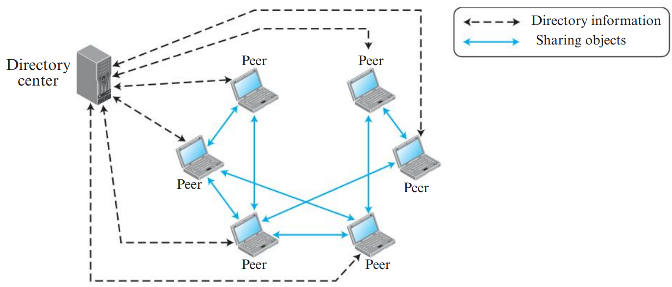
Centralized Directory (Napster): A central server maintains an index of files and peer IP addresses. File transfers occur peer-to-peer.
Drawback: Single point of failure, severe performance bottleneck, vulnerable to legal shutdown.
Unstructured P2P (Gnutella): Completely decentralized with no central directory. Search queries are broadcast using flooding with a Time-to-Live (TTL).
Advantages: Simple to construct; peers can join and leave easily; no central directory needed.
Disadvantages: Flooding creates heavy network traffic; searching is inefficient; poor scalability in large networks.
Structured P2P using Distributed Hash Tables (DHT): Files and nodes are organized deterministically using consistent hashing, guaranteeing that any existing file can be located in \(O(\log N)\) steps!
In unstructured P2P networks (such as early Gnutella), peers connect randomly without a predefined overlay topology:
Query Flooding: When a peer searches for a file, it sends the request to all its directly connected neighbors. Each neighbor searches its local files and forwards the query to all its neighbors, continuing until a Time-To-Live (TTL) hop limit is reached.
Pros: Highly resilient to peer churn (nodes joining/leaving freely); requires no central index server.
Cons: Generates massive duplicate traffic (flooding storms); cannot guarantee finding rare files even if they exist in the network.
Comparison of Distributed Hash Table (DHT) Protocols
DHT Protocol
Identifier Space
Routing Mechanism
Key Location Rule
Prominent Application
Chord
Circular identifier space (Identifier circle) (modulo \(2^m\))
Finger Table (\(O(\log N)\) hops)
Successor node of the key: \(\text{Successor}(\text{Key})\)
Cooperative File System (CFS)
Pastry
128-bit circular space
Prefix-based routing table + Leaf set
Numerically closest live node
PAST storage utility
Kademlia
160-bit space (SHA-1)
Tree-based routing with \(k\)-buckets using XOR metric distance: \(d(x,y) = x \oplus y\)
Node with minimal XOR distance
BitTorrent Mainline DHT, Ethereum
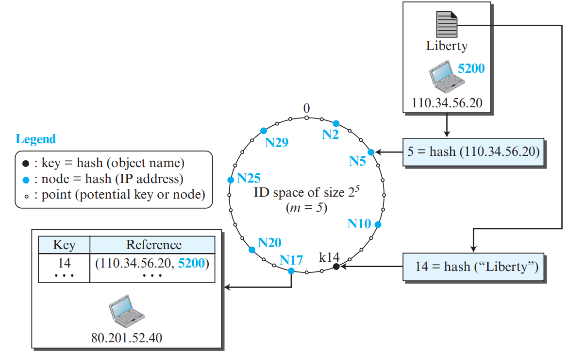
2. Structured P2P: The Chord Protocol & DHT
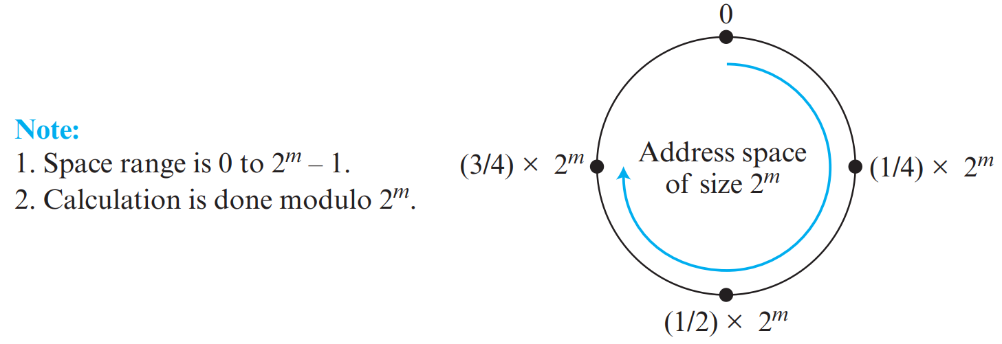
Chord uses a circular 1D identifier space of size \(2^m\) arranged in a logical ring modulo \(2^m\) (identifiers range from \(0\) to \(2^m - 1\)):
A cryptographic hash function (SHA-1) hashes a node's IP address to an \(m\)-bit Node ID.
The same hash function hashes a resource's name/key to an \(m\)-bit Key ID.
Successor Rule: Key \(k\) is assigned to the first node whose identifier is equal to or follows \(k\) in the clockwise direction, denoted as \(\text{successor}(k)\).
Figure 8.2: Circular Identifier Space Modulo 2^m (Page 45)
Figure 8.3: Key Assignment in Chord Ring: Key k14 Stored at Node N17 (Page 46)
If each node only knows its immediate clockwise successor, routing a query takes \(O(N)\) linear hops. To achieve fast \(O(\log N)\) lookups, each node \(n\) maintains a routing table of \(m\) entries called a Finger Table.
The Finger Table Formula: The \(i\)-th entry in the finger table of node \(n\) is:
Lookup Routing: When looking up key \(k\), node \(n\) forwards the query to the closest predecessor of \(k\) in its finger table, halving the remaining distance to the target at each hop!
PART 09EXAMINATION ESSAY • 5M / 9M
Case Study: BitTorrent Protocol
PDF Pages: 47 – 48
💡 What is BitTorrent?
BitTorrent is a wildly successful peer-to-peer file-distribution protocol designed by Bram Cohen. It divides large files into small chunks and uses clever game-theoretic incentives to encourage cooperation and eliminate free riders.
1. Core BitTorrent Terminology
Term
Meaning & Technical Role
Torrent File (.torrent)
A metadata file containing tracker URLs, piece sizes, and cryptographic SHA-1 hashes of all pieces.
Tracker
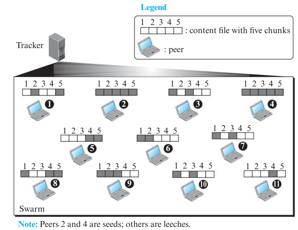
A central coordinating entity that tracks which peers are currently participating in the torrent and gives new peers an initial peer list. (Does not touch file data!).
Swarm
The collective group of all peers actively downloading and uploading pieces of the same file.
Seed
A peer that possesses the complete 100% file and continues uploading to other peers.
Leech
A peer that has only a fraction of the pieces and is actively downloading the remainder.
Piece & Block
File is split into pieces (typically 256 KB to 1 MB); each piece is further divided into blocks (typically 16 KB).
The user obtains the .torrent file from a Web server or magnet link.
The BitTorrent client contacts the Tracker specified in the torrent file.
The Tracker responds with a randomized list of IP addresses of active peers in the swarm.
The client initiates direct TCP connections with peers from the list, discovering which pieces they have.
The client downloads missing pieces while simultaneously uploading pieces it already owns to interested peers.
Once all pieces are downloaded and cryptographically verified, the leecher becomes a Seed.
3. BitTorrent Policies for Fairness & Efficiency (PDF Page 48)
Policy
Working Principle & Why It Is Used
Rarest-First Policy
The peer always requests the pieces that are rarest (held by the fewest peers in the swarm). Why: Rapidly replicates rare pieces so they don't become extinct if a seed leaves, and ensures peers have unique pieces they can trade with others.
Choking & Unchoking
Each peer limits simultaneous upload connections (typically to ~4 peers) to avoid overloading bandwidth. Unchoked peers exchange data; choked peers are temporarily blocked.
Tit-for-Tat (TFT) Policy
Peers unchoke the 4 peers that are currently sending data to them at the highest download rates. Peers that upload fast are rewarded with fast downloads. Prevents "free-riding"!
Optimistic Unchoking
Every 30 seconds, a peer randomly unchokes one additional peer regardless of its upload rate. Why: Allows new peers with zero pieces to bootstrap and download their first piece, and discovers if a random peer has better upload bandwidth.
Endgame Mode
When the last few missing blocks remain, the peer requests them from all connected peers simultaneously to avoid waiting on a slow peer.
📦 Anatomy of a .torrent File & Anti-Snubbing Policy
The .torrent File: A compact bencoded metadata file (.torrent file) that contains:
The Announce URL of the central Tracker.
File information (name, total file size, piece length—typically 256 KB).
A list of 20-byte SHA-1 cryptographic hash digests for every piece, allowing peers to verify data integrity immediately after downloading.
Anti-Snubbing Policy (Anti-snubbing): If a peer stops sending data for more than 60 seconds, it is marked as "snubbed". A snubbed peer is choked, and downloads from it occur only through optimistic unchoking until it resumes reciprocating data.
Endgame Mode: Towards the end of a download when only a few pieces remain, the client sends requests for those remaining pieces to ALL active peers in parallel, discarding duplicate arrivals to prevent a single slow peer from delaying completion.
PART 10EXAM MASTERCLASS • NUMERICALS & QUESTION BANK
Problem: An application on a host generates 1460 bytes of user data. The transport layer uses UDP with an 8-byte header, the network layer adds a 20-byte IP header, and the data link layer adds an Ethernet header and trailer totalling 18 bytes. Calculate:
The total size of the Ethernet frame transmitted over the network.
The overhead efficiency (percentage of the frame that is actual application data).
Step-by-Step Solution:
Given:
Application Data (\(D\)) = 1460 bytes
Transport Header (UDP, \(H_t\)) = 8 bytes
Network Header (IP, \(H_n\)) = 20 bytes
Data Link Header + Trailer (Ethernet, \(H_d\)) = 18 bytes
Problem: A web browser requests an HTML base page that references 5 small embedded image objects. The RTT between client and server is 50 ms. Assuming transmission times and server processing times are negligible, calculate the total retrieval time for:
Non-Persistent HTTP (HTTP/1.0, serial connections).
Persistent HTTP without pipelining (HTTP/1.1).
Persistent HTTP with pipelining (HTTP/1.1).
Step-by-Step Solution:
Given \(N = 5\) objects, \(\text{RTT} = 50\text{ ms}\).
2. Persistent HTTP without Pipelining:
Total time \(= (N + 2)\,\text{RTT} = (5 + 2) \times 50\text{ ms} = 7 \times 50\text{ ms} = \mathbf{350\text{ ms}}\).
3. Persistent HTTP with Pipelining:
Total time \(= 3\,\text{RTT} = 3 \times 50\text{ ms} = \mathbf{150\text{ ms}}\).
KTU Module 1 Comprehensive Question Bank (Theory Only)
Answer:
Control Connection (Port 21): Used for transmitting user credentials, commands (e.g., USER, RETR), and server status replies out-of-band. Remains open throughout the session.
Data Connection (Port 20): Used strictly for transferring the actual file data or directory listings. It is established dynamically on-demand for each transfer and closed immediately upon completion.
Answer:
A cookie is a small piece of state information sent by a server and stored on the client browser. Because HTTP is stateless, the server generates a unique cookie ID and sends it via the Set-Cookie: ID response header. On future visits, the browser automatically includes this ID in the Cookie: ID request header, enabling the server to recognize the returning user and maintain session state.
Answer Blueprint:
Architecture Diagram (2 Marks): Draw Alice (UA) → Alice Mail Server (MTA Client → MTA Server) → Bob Mail Server (MTA Server → Mailbox) → Bob (MAA Client → UA).
User Agent (UA) (1.5 Marks): Software used to compose, read, and organize emails.
Message Transfer Agent (MTA) & SMTP (2.5 Marks): Server-to-server push protocol over TCP port 25. Explain the three phases: connection establishment (HELO), mail transfer (MAIL FROM, RCPT TO, DATA), and termination (QUIT).
Message Access Agent (MAA) & Protocols (2.5 Marks): Pull protocols used by recipient. Differentiate POP3 (port 110, simple download/delete) vs IMAP4 (port 143, server-side folders, multi-device synchronization).
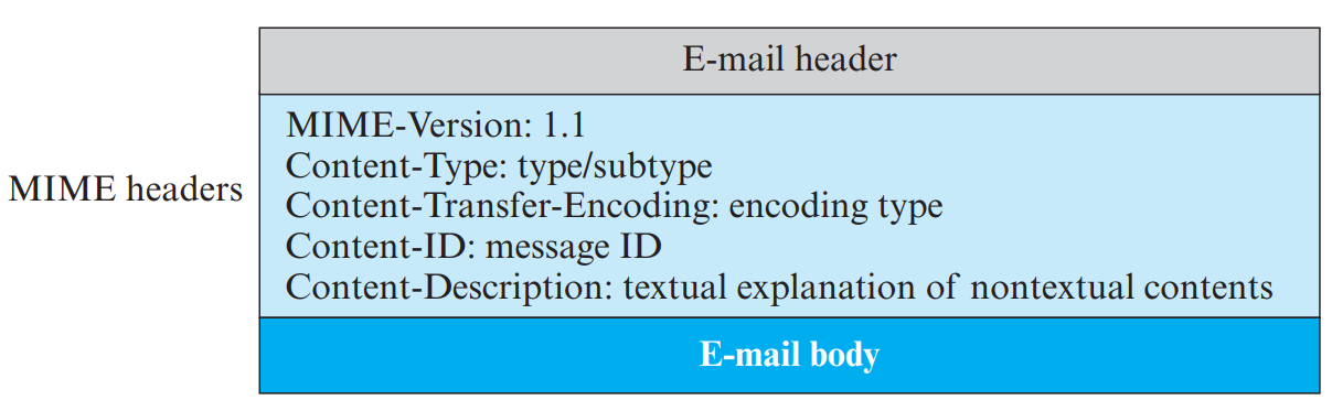
Role of MIME (0.5 Mark): Enables sending non-ASCII and multimedia attachments.
⚡ Module 1 Last-Minute Memory Mnemonics
TCP/IP 5 Layers (Bottom to Top):Please Do Not Throw Sausage Pizza → Physical, Data Link, Network, Transport, Application.
Standard Port Numbers:
FTP Control: 21 | FTP Data: 20
SMTP: 25 | DNS: 53
HTTP: 80 | POP3: 110 | IMAP4: 143
Mesh Links Formula: \(W = \frac{n(n - 1)}{2}\)
Base64 Overhead: 3 bytes in → 4 chars out (33.3% size expansion).