Interactive Study Environment • APJ Abdul Kalam Technological University
KTU 2024 SCHEME
11 CONTACT HOURS
THEORY MASTERCLASS
Module 3: Data Link Layer
Complete, beginner-friendly masterclass covering Framing (Bit/Byte Stuffing), Error Detection (CRC, Hamming Distance), HDLC & PPP, MAC Protocols (Pure/Slotted ALOHA, CSMA/CD, CDMA), ARP & MAC Addressing, Ethernet (802.3) & VLANs, Connecting Devices (Hubs, Switches, Routers), Wireless LANs (802.11, CSMA/CA, RTS/CTS), Bluetooth, and Mobile IP.
66 Pages
Official PDF Notes Synthesized
94 Figures
High-Res Diagrams Embedded
11 Parts
Step-by-Step Learning Progression
100% Theory
Hands-on Code Excluded (KTU Rule)
💡 What is the Data Link Layer?
The Data Link Layer transforms a raw, error-prone physical transmission facility into a reliable link. It provides node-to-node (hop-to-hop) frame delivery across a single physical communication link (cable or wireless).
1. The Two Sublayers: LLC & MAC
In LAN architectures (IEEE 802), the Data Link Layer is divided into two distinct sublayers: Logical Link Control (LLC) and Medium Access Control (MAC):
| Sublayer Name | Position | Primary Responsibilities |
|---|
| Logical Link Control (LLC) |
Upper Sublayer (Below Network Layer) |
Provides flow control, error control, and framing logic; multiplexes multiple network-layer protocols (IPv4, IPv6, ARP) over a common physical link. Independent of transmission medium. |
| Media Access Control (MAC) |
Lower Sublayer (Above Physical Layer) |
Controls which device gets to transmit on a shared medium at any given time (CSMA/CD, CSMA/CA, Token Passing); handles 48-bit physical MAC addressing and frame validation. |
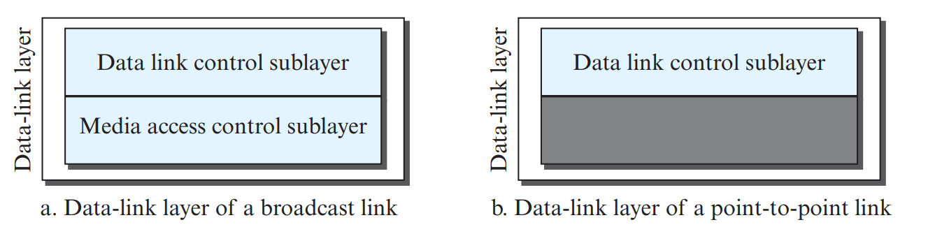
Figure 1.1: Division of Data-Link Layer into LLC and MAC Sublayers (Page 2)
2. Framing: Packaging Packets into Frames
The data link layer separates the continuous bit-stream received from the physical layer into discrete units called frames. The two foundational framing approaches are:
A. Byte-Oriented (Character-Oriented) Framing & Byte Stuffing
Data is carried as a sequence of 8-bit bytes. Special 1-byte delimiter patterns called Flags mark the start and end of a frame (e.g., FLAG = 01111110 or ASCII DLE STX / DLE ETX).
- The Problem: What happens if the actual user payload (e.g., an image, video, or binary file) contains a byte that looks identical to the Flag byte? The receiver will misinterpret it as the end of the frame!
- Byte Stuffing: Whenever a Flag byte or an Escape (ESC) byte appears naturally inside the data, the sender inserts an extra Escape (ESC) byte immediately before it. The receiver strips the ESC byte and recovers the original data unaltered.
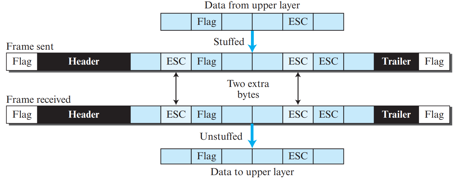
Figure 1.2: Byte Stuffing and Un-stuffing Mechanism with ESC Bytes (Page 3)
B. Bit-Oriented Framing & Bit Stuffing
Data is viewed as an arbitrary stream of individual bits. Standard bit-oriented protocols (like HDLC) use the 8-bit flag 01111110 (six consecutive 1s bounded by 0s) to delimit frames.
- Bit Stuffing Rule: Whenever the sender encounters five consecutive 1s in the data stream, it automatically stuffs a 0 bit immediately after the fifth 1 (even if the next bit was already 0).
- Bit Un-stuffing: Whenever the receiver encounters five consecutive 1s followed by a 0, it strips that stuffed 0 bit. If followed by a 1 and then 0, it recognizes the true Flag!
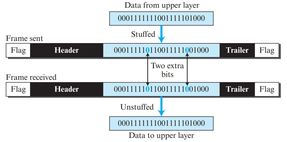
Figure 1.3: Bit Stuffing: Inserting '0' After Every Five Consecutive '1's (Page 4)
⭐ High-Frequency KTU Question: Byte Stuffing vs. Bit Stuffing
| Parameter | Byte Stuffing | Bit Stuffing |
|---|
| Unit of Operation | Entire 8-bit bytes (characters). | Individual single bits. |
| Stuffed Symbol | An 8-bit ESC (Escape) byte. | A single '0' bit. |
| Condition for Stuffing | When data byte matches Flag or ESC byte. | After five consecutive '1's in data stream. |
| Overhead | 8 bits per escape (high overhead). | 1 bit per 5 ones (very low overhead). |
💡 Why Error Detection?
Electromagnetic interference, thermal noise, and attenuation corrupt bits during transmission. Error detection enables the receiver to discover when corrupted bits exist. Error correction allows the receiver to reconstruct the original bits without retransmission.
1. Types of Errors & Hamming Distance
- Single-Bit Error: Only 1 bit in a given data unit is altered from 1 to 0 or 0 to 1.
- Burst Error: 2 or more bits in the data unit have changed. The length of the burst is measured from the first damaged bit to the last damaged bit (even if some intermediate bits are undamaged).
📐 Hamming Distance Rules for Error Detection & Correction
The Hamming Distance \(d(x, y)\) between two codewords of equal length is the number of bit positions where the corresponding bits differ. The minimum Hamming distance \(d_{\text{min}}\) (d_min / \(d_{\min}\)) of a code dictates its power:
- To guarantee detecting up to \(s\) bit errors:
\[d_{\text{min}} \ge s + 1\]
- To guarantee correcting up to \(t\) bit errors:
\[d_{\text{min}} \ge 2t + 1\]
Example: To correct 2-bit errors (\(t = 2\)), the minimum Hamming distance must be \(d_{\text{min}} \ge 2(2) + 1 = 5\).
🔍 Parity Check Schemes: Simple Parity & Two-Dimensional Parity
Before advanced polynomial codes like CRC, linear block parity codes provided elementary error detection:
- Simple Parity Check (Simple parity): A single redundant bit (parity bit) is appended to a k-bit dataword so the total number of 1s is even (even parity) or odd (odd parity).
- Hamming Distance: \(d_{\min} = 2\). Can detect any odd number of bit errors (guaranteed detection of 1-bit errors). Fails completely if an even number of bits flip (e.g. 2-bit error).
- Two-Dimensional Parity Check (Two-dimensional parity): Data is organized into a 2D matrix (rows and columns). A parity bit is calculated for every row (Row parity) AND for every column (Column parity).
- Detection & Correction Power: Can detect any pattern of up to 3 bit errors. Can correct single-bit errors without retransmission by finding the intersection of the erroneous row and column!
🔢 Internet Checksum Algorithm
The Internet Checksum is based on One's complement addition of 16-bit words:
- The sender divides the data into a sequence of 16-bit words.
- All 16-bit words are summed using one's complement arithmetic (any carry out of the most significant bit is added back to the least significant bit).
- The sum is complemented (bitwise NOT) to form the checksum and transmitted with the data.
- The receiver adds all received 16-bit words, including the checksum. If the result is all 1s (which complements to zero), the data is accepted; otherwise, it is rejected.
2. Cyclic Redundancy Check (CRC) Masterclass
CRC is the most powerful and widely used error-detection code in computer networks (used in Ethernet, Wi-Fi, HDLC). It uses modulo-2 binary division (where addition and subtraction are identical to bitwise XOR).
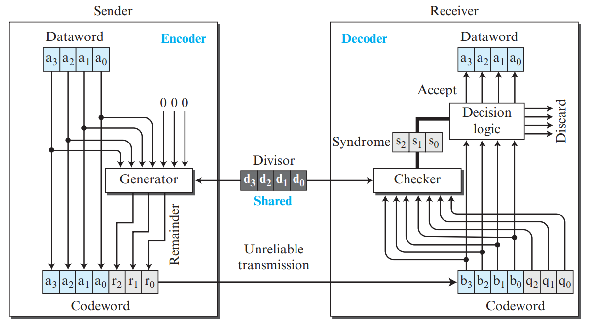
Figure 2.1: CRC Binary Division at Sender (Page 8)
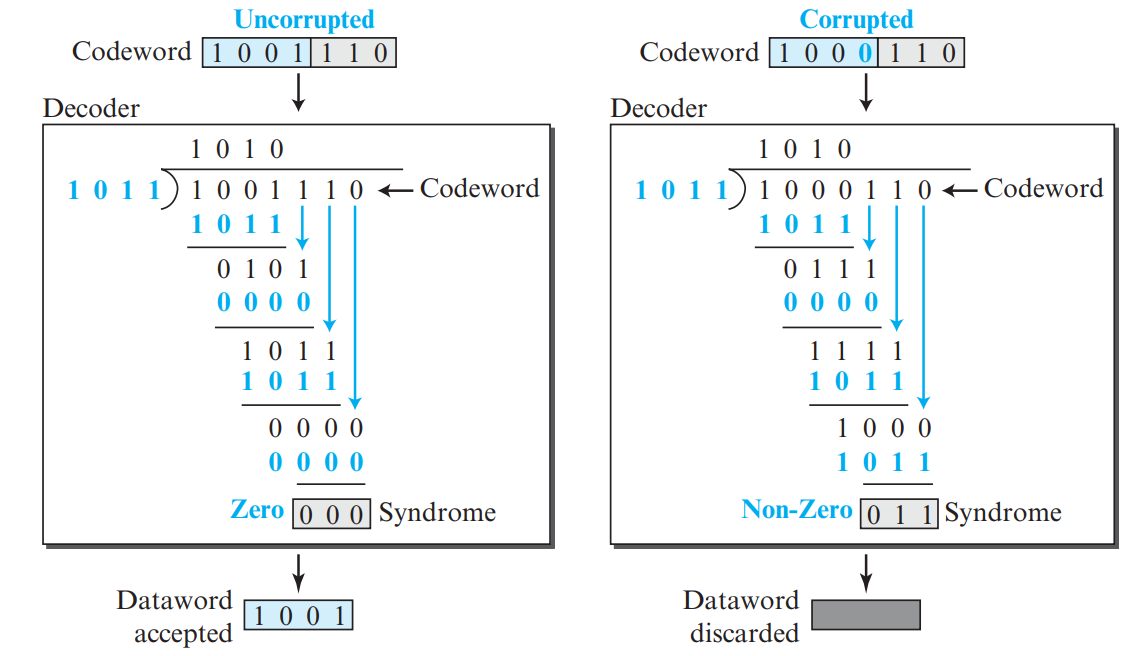
Figure 2.2: CRC Error Verification at Receiver (Page 8)
📐 High-Frequency KTU Numerical Problem: Complete CRC Calculation
Problem: A data unit 110101 is to be transmitted using CRC with the generator polynomial \(G(x) = x^3 + x + 1\). Find:
- The divisor bit string.
- The CRC bits (remainder) and the transmitted codeword.
- The verification at the receiver when received without error, and when bit 3 is inverted.
Step-by-Step Solution:
1. Divisor from Polynomial:
\(G(x) = 1 \cdot x^3 + 0 \cdot x^2 + 1 \cdot x^1 + 1 \cdot x^0 \implies \mathbf{1011}\) (Degree \(n = 3\)).
2. Appending Zeros to Dataword:
Degree of generator is 3, so append \(3\) zeros to dataword 110101 \(\implies\) 110101000.
3. Modulo-2 Division at Sender:
            110000  (Quotient)
    1011 | 110101000
           1011
           -----
            1100
            1011
            ----
             1111
             1011
             ----
              1000
              1011
              ----
               0110
               0000
               ----
                1100
                1011
                ----
                 001  (Remainder = CRC bits!)
Remainder = \(\mathbf{001}\).
Codeword Transmitted: \(\text{Data} + \text{CRC} = 110101 + 001 = \mathbf{110101001}\).
4. Verification at Receiver (No Error):
Divide received codeword 110101001 by 1011. The remainder is strictly \(\mathbf{000}\) \(\implies\) Data is ACCEPTED without error!
5. Verification with Error:
If a bit is flipped (e.g., 110111001), the remainder is non-zero (syndrome \(\ne 0\)) \(\implies\) Error detected! Data is REJECTED.
3. Standard Polynomials
| Name | Polynomial Expression | Bit Pattern | Standard Use |
|---|
CRC-8 | \(x^8 + x^2 + x + 1\) | 100000111 | ATM cells |
CRC-16 | \(x^{16} + x^{15} + x^2 + 1\) | 11000000000000101 | HDLC, USB |
CRC-32 | \(x^{32} + x^{26} + x^{23} + \dots + 1\) | 33 bits | Ethernet (802.3), Wi-Fi (802.11) |
💡 What is Data Link Control (DLC)?
DLC refers to the procedures and protocols used to manage reliable, structured communication between two directly connected nodes over a point-to-point or multipoint link.
3. Data Link Control (DLC) Flow & Error Control Protocols
Data Link Control provides reliable point-to-point transfer across an individual link using Sliding Window flow control mechanisms:
| Protocol | Sender Window Size (\(W_s\)) | Receiver Window Size (\(W_r\)) | Sequence Number Space (\(m\)) | Retransmission Behavior |
|---|
| Stop-and-Wait ARQ | 1 | 1 | \(\ge 2\) (0 and 1) | Transmits 1 frame, waits for ACK before sending next. Simple but inefficient on long links. |
| Go-Back-N (GBN) ARQ | \(2^m - 1\) | 1 | \(2^m\) | Receiver accepts only strictly in-order frames; discards out-of-order frames. Sender retransmits all unacknowledged frames starting from the lost one. |
| Selective Repeat ARQ | \(2^{m-1}\) | \(2^{m-1}\) | \(2^m\) | Receiver buffers out-of-order frames. Sender retransmits ONLY the specific frames reported lost via Negative ACK (NAK). Maximum efficiency. |
Piggybacking: A bidirectional optimization where an acknowledgment (ACK) is embedded directly into the header of an outgoing data frame traveling in the reverse direction, saving substantial bandwidth compared to sending dedicated ACK frames.
1. High-Level Data Link Control (HDLC)
🏢 HDLC Station Types & Transfer Modes
- Primary Station: Controls link operation; issues commands.
- Secondary Station: Operates under primary station control; issues only responses.
- Combined Station: Acts as both primary and secondary; can issue both commands and responses in balanced configurations.
HDLC is an ISO-standard bit-oriented protocol for point-to-point and multipoint communication. It defines two operational modes:
- Normal Response Mode (NRM): Unbalanced configuration. One primary station commands; secondary stations can only respond when polled.
- Asynchronous Balanced Mode (ABM): Balanced configuration. Both stations are combined peers and can initiate communication independently without permission. Used on point-to-point links!
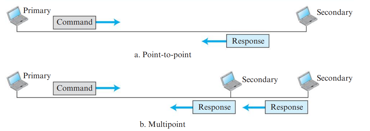
Figure 3.1: HDLC Station Configurations: NRM and ABM (Page 12)
The Three HDLC Frame Types (PDF Page 13)

Figure 3.2: HDLC Frame Formats: I-Frame, S-Frame, and U-Frame (Page 12)
| Frame Type | First Bit Pattern | Purpose & Functionality |
|---|
| I-Frame (Information) |
Starts with 0 |
Carries user application data from the network layer. Contains sender sequence number \(N(S)\) and piggybacked acknowledgment \(N(R)\). |
| S-Frame (Supervisory) |
Starts with 10 |
Carries flow and error control information when there is no user data to piggyback on: RR (Receive Ready), RNR (Receive Not Ready), REJ (Reject), and SREJ (Selective Reject). |
| U-Frame (Unnumbered) |
Starts with 11 |
Carries link setup, mode negotiation, disconnection, and network management commands (e.g., SABM, DISC). |
2. Point-to-Point Protocol (PPP)
PPP is the dominant byte-oriented data link protocol used for establishing direct connections between two nodes (e.g., home PC to ISP via DSL or dial-up).
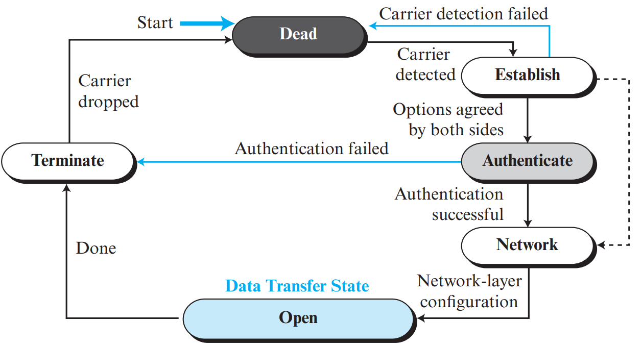
Figure 3.3: PPP Transition State Machine (Page 15)
PPP Authentication Protocols: PAP vs. CHAP (PDF Page 16)
| Parameter | Password Authentication Protocol (PAP) | Challenge Handshake Authentication Protocol (CHAP) |
|---|
| Handshake Type | Simple Two-Way Handshake. | Secure Three-Way Handshake. |
| Password Security | Sends username and password in clear plaintext across the link! Highly vulnerable to sniffing. | Password is NEVER transmitted over the wire! |
| Working Mechanism | Client sends password; server accepts or rejects. | Server sends random "Challenge"; client hashes Challenge + Password (MD5) and returns response; server verifies hash. |
| Repeated Authentication | Only once at connection setup. | Server can send fresh challenges periodically to prevent spoofing. |
⚙️ Point-to-Point Protocol (PPP) Core Architecture: LCP and NCP
PPP relies on two main protocol suites to control link establishment and network negotiation:
- Link Control Protocol (LCP): Responsible for establishing, configuring, testing, maintaining, and terminating the physical data link connection. LCP negotiates Maximum Receive Unit (MRU), authentication protocols, and compression.
- Network Control Protocol (NCP): A family of protocols designed to negotiate network-layer parameters for specific layer-3 protocols. For IP networks, PPP invokes IPCP (Internet Protocol Control Protocol) to dynamically assign IP addresses to clients.
- Authentication Schemes:
- PAP (Password Authentication Protocol): Two-way handshake; sends plaintext username and password (insecure).
- CHAP (Challenge Handshake Authentication Protocol): Three-way handshake; uses cryptographic MD5 challenge-response hash, preventing eavesdropping and replay attacks.
💡 Why Multiple Access Protocols?
When multiple stations share a single broadcast transmission medium (like a common cable or the airwaves), multiple simultaneous transmissions collide and corrupt data. Multiple Access protocols regulate access to prevent or resolve collisions.
1. ALOHA Protocols: Pure ALOHA vs. Slotted ALOHA
| Parameter | Pure ALOHA | Slotted ALOHA |
|---|
| Transmission Rule | Any station can transmit at any arbitrary time whenever it has data ready. | Time is divided into discrete slots equal to frame time \(T_{fr}\). Stations can only transmit at the start of a slot. |
| Vulnerable Period (\(V_t\)) | \(V_t = 2 \times T_{fr}\) (Frames collide if sent within \(2 T_{fr}\)). | \(V_t = 1 \times T_{fr}\) (Vulnerable window is halved!). |
| Throughput Formula (\(S\)) | \(S = G \cdot e^{-2G}\) | \(S = G \cdot e^{-G}\) |
| Maximum Throughput | 18.4% (at load \(G = 0.5\): \(S_{\text{max}} = \frac{1}{2e} \approx 0.184\)). | 36.8% (at load \(G = 1.0\): \(S_{\text{max}} = \frac{1}{e} \approx 0.368\)). |
| Synchronization | None needed. | Requires global master clock synchronization among all stations. |
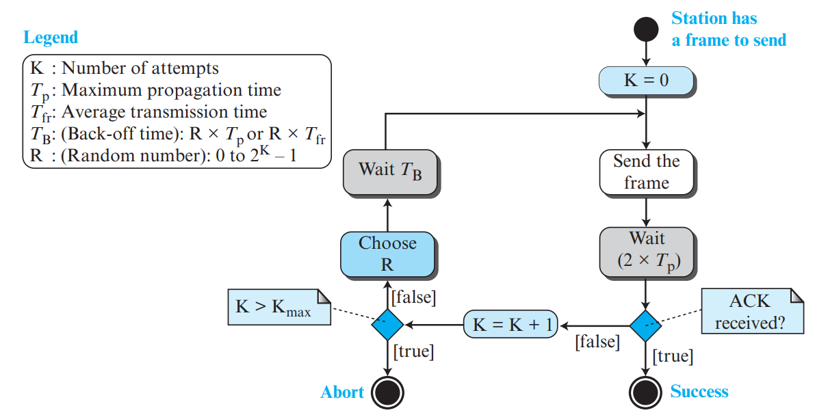
Figure 4.1: Vulnerable Time Comparison: Pure ALOHA (2*Tfr) vs. Slotted ALOHA (Tfr) (Page 18)
📐 High-Frequency KTU Numerical Problem: Pure ALOHA Throughput
Problem: A pure ALOHA network transmits 200-bit frames on a shared channel of 200 kbps. Find the throughput if the system produces 500 frames per second.
Solution:
- Frame transmission time:
\[T_{fr} = \frac{\text{Frame Length}}{\text{Bandwidth}} = \frac{200 \text{ bits}}{200 \times 10^3 \text{ bps}} = 10^{-3} \text{ s} = 1 \text{ ms}\]
- Average load \(G\) (frames generated per frame transmission time):
\[G = \text{Frame Generation Rate } (\lambda) \times T_{fr} = 500 \text{ frames/s} \times 10^{-3} \text{ s} = \mathbf{0.5}\]
- Throughput \(S\) for Pure ALOHA:
\[S = G \cdot e^{-2G} = 0.5 \cdot e^{-2(0.5)} = 0.5 \cdot e^{-1} = \frac{0.5}{2.71828} \approx \mathbf{0.1839 \text{ (18.39\%)}}\]
- Actual throughput in frames/s: \(500 \times 0.1839 = \mathbf{91.95 \text{ frames/s}}\).
2. Carrier Sense Multiple Access (CSMA) & Persistence Methods
Principle: "Sense before transmit." Stations listen to the medium before sending. If the channel is busy, stations defer transmission according to one of three persistence strategies:
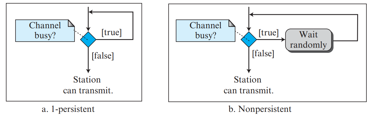
Figure 4.2: CSMA Persistence Strategies: 1-Persistent, Non-Persistent, and p-Persistent (Page 22)
| Persistence Method | Behavior When Medium is Busy | Collision Probability | Channel Idle Time |
|---|
| 1-Persistent |
Continuously senses channel; transmits immediately (with probability 1) as soon as channel becomes idle. |
Highest (If 2 stations wait for channel to clear, both transmit simultaneously upon idle \(\rightarrow\) collision!). |
Lowest (zero channel idle time). |
| Non-Persistent |
If busy, waits a random amount of time before sensing again. |
Lowest (reduces collisions drastically). |
Highest (channel may sit idle while stations are waiting their timers). |
| p-Persistent |
Continuously senses. When idle, transmits with probability \(p\), or defers to next slot with probability \((1-p)\). |
Balanced & Tunable (controlled by parameter \(p\)). |
Optimal compromise between collision rate and idle time. |
3. CSMA with Collision Detection (CSMA/CD) & Random Access
Principle: "Sense before transmit, and LISTEN WHILE TRANSMITTING." Used in traditional half-duplex Ethernet (IEEE 802.3).
- A station transmits while continuously monitoring its own transmission.
- If signal energy on the cable exceeds normal threshold, a collision is detected!
- Station aborts transmission immediately, broadcasts an 8-byte Jamming Signal to warn all other nodes, and waits a random back-off time using the Binary Exponential Back-Off Algorithm.
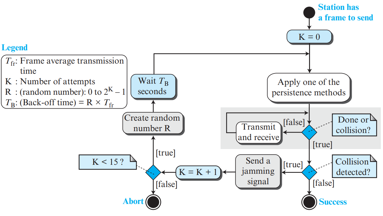
Figure 4.3: CSMA/CD Operation Flowchart (Page 24)
📐 High-Frequency KTU Derivation: Minimum Frame Size in CSMA/CD
Why is a minimum frame length mandatory in CSMA/CD?
Suppose Station A sends a packet to Station B at the farthest end of the cable (propagation time \(T_p\)). Just before the packet arrives, Station B senses the channel as idle and starts transmitting, causing a collision at time \(T_p\). The collision signal takes another \(T_p\) to travel back to Station A. Therefore, Station A can only detect the collision after a round-trip propagation time of \(2 \times T_p\)!
To ensure Station A is still actively transmitting when the collision signal returns (so it knows its own frame collided), the frame transmission time \(T_{fr}\) must satisfy:
\[T_{fr} \ge 2 \times T_p\]
Since \(T_{fr} = \frac{\text{Frame Size } (L)}{\text{Bandwidth } (B)}\), the Minimum Frame Size is:
\[L_{\text{min}} = 2 \times T_p \times B\]
Example: For Standard 10 Mbps Ethernet with maximum network propagation delay \(T_p = 25.6\ \mu\text{s}\):
\[L_{\text{min}} = 2 \times (25.6 \times 10^{-6}\text{ s}) \times (10 \times 10^6\text{ bps}) = 512\text{ bits} = \mathbf{64\text{ bytes!}}\]
This is why Ethernet frames can NEVER be smaller than 64 bytes (512 bits)!
⏱️ CSMA/CD Binary Exponential Backoff Algorithm & Contention Window
When two or more stations transmit simultaneously, a collision occurs. CSMA/CD handles retransmission attempts using the Binary Exponential Backoff (Exponential backoff) algorithm:
- Initialize collision counter \(k = 0\).
- Upon each collision, increment \(k = k + 1\).
- Randomly choose a backoff integer \(R\) from the Contention Window range:
\[0 \le R \le 2^k - 1\]
- For \(k > 10\), the maximum contention window is capped at \(2^{10} - 1 = 1023\).
- Wait for backoff duration \(T_B = R \times \text{Slot Time}\) (where Slot Time for Standard Ethernet = 512 bit times = \(51.2\ \mu\text{s}\)).
- If \(k\) reaches 15 (or 16), abort transmission and report link failure to upper layers.
1. Controlled Access Protocols
- Reservation: Stations divide time into intervals. In each interval, a reservation frame precedes data frames; stations reserve slots in advance.
- Polling: One primary device coordinates communication with secondary devices.
- Poll: Primary asks secondary if it has data to send.
- Select: Primary alerts secondary that it is about to receive data.
- Token Passing: Stations are organized in a logical ring. A special small frame called the Token circulates. Only the station holding the token is permitted to transmit. Eliminates collisions entirely!
2. Channelization: FDMA, TDMA & CDMA Masterclass
Channelization protocols divide the total available link bandwidth among multiple stations:
| Method | Division Principle | Interference Prevention | Efficiency |
|---|
| FDMA (Frequency-Division Multiple Access) | Total frequency band split into distinct frequency channels. | Guard bands between adjacent frequencies prevent crosstalk. | Wasted bandwidth if a assigned station is idle. |
| TDMA (Time-Division Multiple Access) | Entire frequency band allocated to each station for a dedicated time slot. | Guard times and synchronization preambles prevent overlap. | Wasted time slots when a station has no traffic. |
| CDMA (Code-Division Multiple Access) | All stations transmit simultaneously across the entire frequency spectrum using unique mathematical codes. | Each station is assigned an Orthogonal Sequence (Chipping Code). | Maximum spectral efficiency; used in 3G cell networks. |
CDMA Mathematical Principles & Walsh Tables
In CDMA, each station \(i\) is assigned a unique \(N\)-bit chip sequence \(\mathbf{C}_i\) chosen from a Walsh Table. Key mathematical properties of orthogonal sequences:
- Self Inner Product: \(\mathbf{C}_i \cdot \mathbf{C}_i = N\) (multiplying a sequence by itself yields \(N\)).
- Cross Inner Product (Orthogonality): \(\mathbf{C}_i \cdot \mathbf{C}_j = 0\) for \(i \ne j\) (multiplying two different sequences yields 0).
Walsh Matrix Generation: \(W_1 = [+1]\), and \(W_{2N} = \begin{bmatrix} W_N & W_N \\ W_N & -W_N \end{bmatrix}\):
\[W_2 = \begin{bmatrix} +1 & +1 \\ +1 & -1 \end{bmatrix}, \quad W_4 = \begin{bmatrix} +1 & +1 & +1 & +1 \\ +1 & -1 & +1 & -1 \\ +1 & +1 & -1 & -1 \\ +1 & -1 & -1 & +1 \end{bmatrix}\]
📝 Worked Numerical Example: CDMA Decoding
Suppose Station 1 has code \(\mathbf{C}_1 = [+1, +1, +1, +1]\) and sends data bit 0 (represented as \(-1\)), so sent signal is \(\mathbf{S}_1 = [-1, -1, -1, -1]\).
Station 2 has code \(\mathbf{C}_2 = [+1, -1, +1, -1]\) and sends data bit 1 (represented as \(+1\)), so sent signal is \(\mathbf{S}_2 = [+1, -1, +1, -1]\).
On the shared channel, signals add linearly: \(\mathbf{S}_{\text{channel}} = \mathbf{S}_1 + \mathbf{S}_2 = [0, -2, 0, -2]\).
To recover Station 1's data, the receiver computes the inner product with \(\mathbf{C}_1\):
\[\mathbf{S}_{\text{channel}} \cdot \mathbf{C}_1 = (0)(1) + (-2)(1) + (0)(1) + (-2)(1) = -4\]
Dividing by \(N = 4\): \(-4 / 4 = -1 \implies \text{Data Bit 0}\) correctly decoded!
In CDMA, all stations transmit simultaneously over the exact same frequency band. Transmissions do not interfere because each station is assigned a unique, mathematically orthogonal code vector (chip sequence).
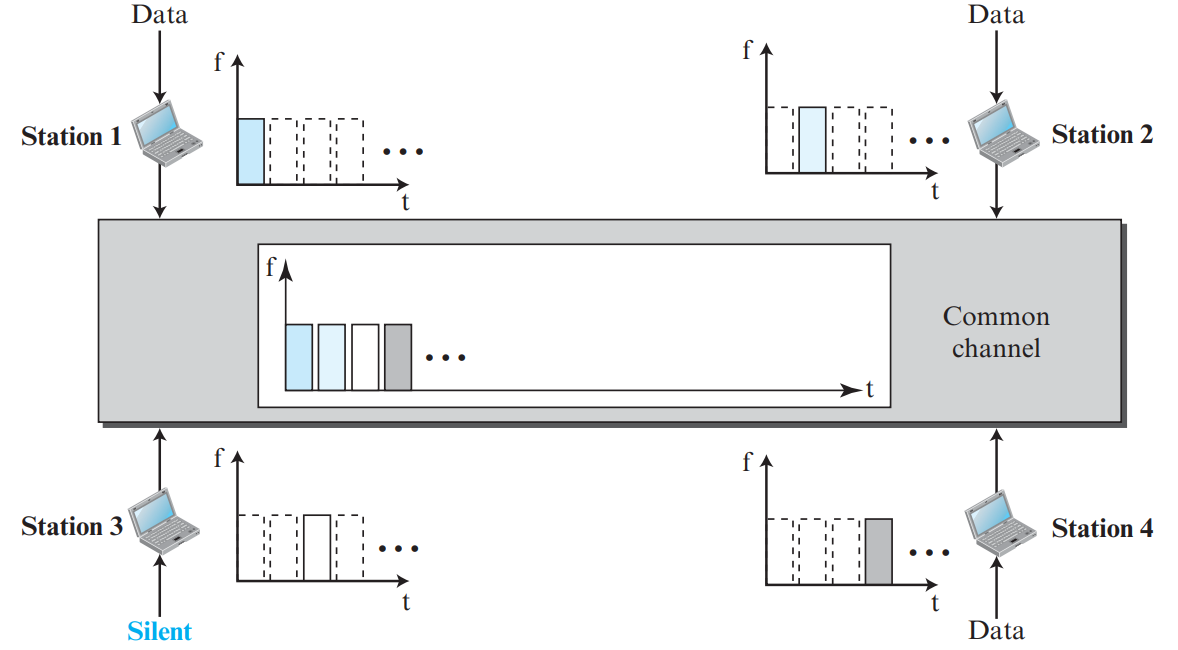
Figure 5.1: CDMA Orthogonal Chip Sequences and Common Channel Combining (Page 28)
⭐ Mathematical Rules of CDMA Orthogonal Vectors
Let \(\mathbf{C}_i\) and \(\mathbf{C}_j\) be chip sequences of length \(N\) assigned to stations \(i\) and \(j\):
- Inner product with another station: \(\mathbf{C}_i \cdot \mathbf{C}_j = 0\) (Orthogonality).
- Inner product with itself: \(\mathbf{C}_i \cdot \mathbf{C}_i = N\).
Decoding at Receiver: If the common channel signal is \(\mathbf{S} = d_1 \mathbf{C}_1 + d_2 \mathbf{C}_2 + \dots + d_k \mathbf{C}_k\), a receiver wanting data from station 1 computes:
\[\frac{\mathbf{S} \cdot \mathbf{C}_1}{N} = \frac{d_1 (\mathbf{C}_1 \cdot \mathbf{C}_1) + 0 + \dots + 0}{N} = \frac{d_1 \cdot N}{N} = \mathbf{d_1}\]
All other stations' signals vanish to zero!
Walsh Tables for Chip Sequence Generation
Walsh tables are generated recursively:
\[W_1 = [ +1 ], \quad W_{2N} = \begin{bmatrix} W_N & W_N \\ W_N & \overline{W_N} \end{bmatrix}\]
For \(N = 4\):
        W4 = [
          [ +1, +1, +1, +1 ],   (Station 1)
          [ +1, -1, +1, -1 ],   (Station 2)
          [ +1, +1, -1, -1 ],   (Station 3)
          [ +1, -1, -1, +1 ]    (Station 4)
        ]
💡 Why Do We Need Both IP and MAC Addresses?
An IP address is a logical address that defines the ultimate source and destination endpoints of a journey across the global Internet. A MAC (Physical) address is a 48-bit hardware address burnt into the NIC that identifies the machine within the current local network hop. As a packet travels across routers, the IP addresses remain constant, but the source and destination MAC addresses change at every single hop!
🏷️ MAC Address Categories: Unicast, Multicast & Broadcast
- Unicast: Delivered to a single specific station. The least significant bit (LSB) of the first byte is 0 (e.g.,
00:1A:2B:3C:4D:5E).
- Multicast: Delivered to a group of subscribed stations. The LSB of the first byte is 1 (e.g.,
01:00:5E:00:00:01).
- Broadcast: Delivered to all stations on the local network. All 48 bits are set to 1 (
FF:FF:FF:FF:FF:FF).
1. Address Resolution Protocol (ARP) Operation
When Host A wants to send an IP datagram to Host B on the same local network, it knows Host B's IP address (from DNS or configuration), but does not know Host B's physical MAC address. Host A uses ARP to resolve the IP address to a MAC address:
-
ARP Request (Broadcast): Host A broadcasts an ARP Request packet across the local LAN: "Who has IP address 192.168.1.5? Please tell MAC 00:1A:2B:3C:4D:5E." Since the destination MAC is broadcast (
FF:FF:FF:FF:FF:FF), all stations on the LAN receive and inspect it.
-
ARP Reply (Unicast): Host B recognizes its own IP address, while all other hosts discard the request. Host B replies directly to Host A with a unicast ARP Reply containing its physical MAC address.
-
ARP Caching: Host A saves this mapping in its local ARP Cache table with a TTL timer to avoid repeating queries for future packets.
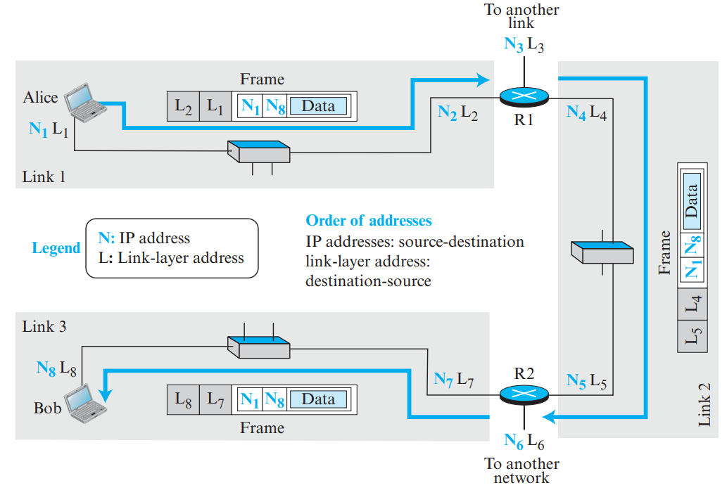
Figure 6.1: ARP Operation: Broadcast Request and Unicast Reply (Page 31)
2. ARP Packet Format
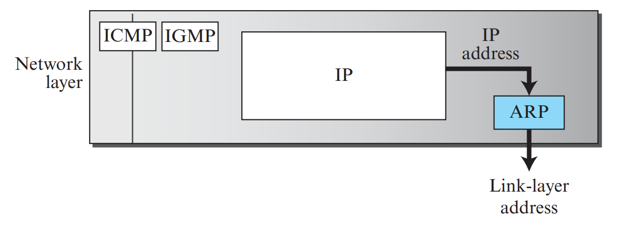
Figure 6.2: ARP Packet Format (Page 32)
| Field Name | Length | Description & Example Value |
|---|
| Hardware Type (HTYPE) | 16 bits | Defines link-layer network type (Ethernet = 1). |
| Protocol Type (PTYPE) | 16 bits | Defines higher-layer protocol (IPv4 = 0x0800). |
| Hardware Length (HLEN) | 8 bits | Length of physical MAC address in bytes (Ethernet = 6). |
| Protocol Length (PLEN) | 8 bits | Length of logical IP address in bytes (IPv4 = 4). |
| Operation (OPER) | 16 bits | 1 for ARP Request; 2 for ARP Reply. |
| Sender Hardware Address (SHA) | 48 bits (6B) | MAC address of the sending station. |
| Sender Protocol Address (SPA) | 32 bits (4B) | IP address of the sending station. |
| Target Hardware Address (THA) | 48 bits (6B) | All 0s in Request; Target station's MAC in Reply. |
| Target Protocol Address (TPA) | 32 bits (4B) | IP address of the requested station. |
💡 What is Ethernet?
Ethernet (IEEE 802.3) is the universally dominant wired LAN technology. Conceived by Bob Metcalfe at Xerox PARC in the 1970s, it evolved from 10 Mbps coaxial bus systems to 100 Gbps switched optical architectures.
1. Standard Ethernet Frame Format (IEEE 802.3)
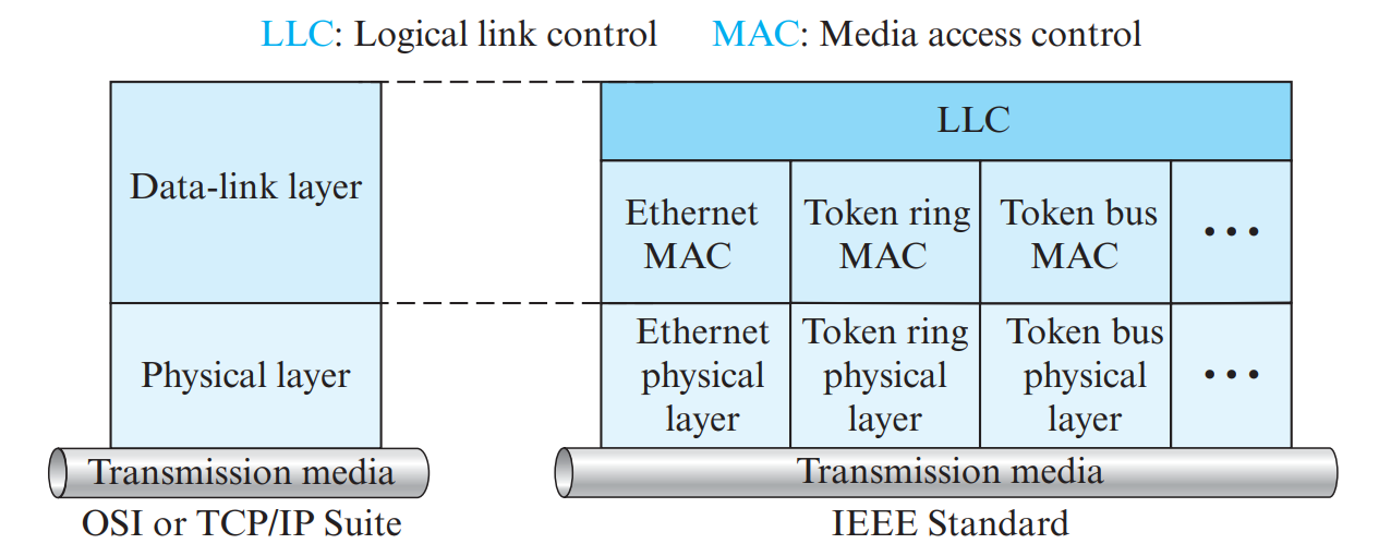
Figure 7.1: Standard Ethernet (802.3) Frame Format (Page 37)
| Field Name | Size | Technical Description |
|---|
| Preamble | 7 bytes | Pattern of alternating 1s and 0s (10101010...) to synchronize receiver clock timing. |
| Start Frame Delimiter (SFD) | 1 byte | Pattern 10101011; the ending double-1 signals that actual frame fields begin immediately. |
| Destination MAC Address | 6 bytes (48 bits) | Physical hardware address of destination NIC. |
| Source MAC Address | 6 bytes (48 bits) | Physical hardware address of sending NIC. |
| Type / Length | 2 bytes | If value \(\ge 1536\) (e.g., 0x0800), defines higher-layer protocol (IPv4). If \(\le 1500\), defines payload length in bytes. |
| Data and Padding | 46 to 1500 bytes | Carries IP packet. If payload is less than 46 bytes, padding bytes are appended to satisfy the 64-byte minimum frame size! |
| CRC / FCS | 4 bytes (32 bits) | Cyclic Redundancy Check (CRC-32) to detect transmission bit errors. |
⭐ Total Frame Length Range in Standard Ethernet
Excluding the 8-byte physical synchronization header (Preamble + SFD):
- Minimum Frame Length: \(6 + 6 + 2 + 46 + 4 = \mathbf{64 \text{ bytes}}\).
- Maximum Frame Length: \(6 + 6 + 2 + 1500 + 4 = \mathbf{1518 \text{ bytes}}\).
2. Evolution of Ethernet: Fast, Gigabit & 10-Gigabit Ethernet
Standard Ethernet evolved across four major generations while maintaining the exact same IEEE 802.3 MAC frame format:
| Generation | Data Rate | Medium & Standards | Line Encoding Scheme | Duplex / Access Method |
|---|
| Standard Ethernet | 10 Mbps | 10Base5 (thick coax), 10Base2 (thin coax), 10Base-T (UTP) | Manchester encoding | Half-duplex CSMA/CD or Full-duplex |
| Fast Ethernet | 100 Mbps | 100Base-TX (2 pairs Cat 5 UTP), 100Base-FX (2 fiber strands), 100Base-T4 (4 pairs Cat 3) | 4B5B + MLT-3 (100Base-TX)
4B5B + NRZ-I (100Base-FX) | Autonegotiation; star topology with switches/hubs |
| Gigabit Ethernet | 1000 Mbps | 1000Base-SX (short-wave fiber), 1000Base-LX (long-wave fiber), 1000Base-T (4 pairs Cat 5e) | 8B/10B + NRZ (optical)
4D-PAM5 (twisted-pair copper) | Full duplex switched (CSMA/CD optional with carrier extension) |
| 10-Gigabit Ethernet | 10 Gbps | 10GBase-SR, 10GBase-LR, 10GBase-ER, 10GBase-EW. Supports LAN PHY (standard LANs) and WAN PHY (compatible with SONET OC-192). | 64B66B encoding (64B/66B) | Exclusively full-duplex star; CSMA/CD completely removed |
3. Physical Layer Implementations of 10 Mbps Ethernet
| Standard | Transmission Medium | Topology | Max Segment Length | Connector |
|---|
| 10Base5 (Thicknet) | Thick coaxial cable (RG-8, 10 mm) | Bus | 500 meters | Vampire tap & AUI cable |
| 10Base2 (Thinnet / Cheapernet) | Thin coaxial cable (RG-58, 5 mm) | Bus | 185 meters | BNC T-connector |
| 10Base-T | Unshielded Twisted Pair (Cat 3/5 UTP) | Star (Hub/Switch) | 100 meters | RJ-45 connector |
| 10Base-F | Optical fiber pair (850 nm multimode) | Star | 2000 meters | ST or SC connector |
4. Virtual Local Area Networks (VLANs)
🏷️ IEEE 802.1Q Frame Tagging & Trunk Links
VLANs segment broadcast domains logically across physical switches:
- IEEE 802.1Q Standard: Defines an explicit 4-byte VLAN tag inserted into the Ethernet frame header between the Source MAC address and EtherType fields. Contains a 12-bit VLAN Identifier (VID), supporting up to 4096 distinct VLANs.
- Access Links vs. Trunk Links:
- Access Link: Connects a standard end device (PC, printer) to a switch port. Carries standard untagged Ethernet frames.
- Trunk Link: Connects two VLAN-aware switches or a switch to a router. Carries multiplexed frames for multiple VLANs using 802.1Q tags to distinguish traffic.
A VLAN is a logical grouping of network devices configured through switch software to communicate as if they were attached to the same physical cable, regardless of their actual physical location.
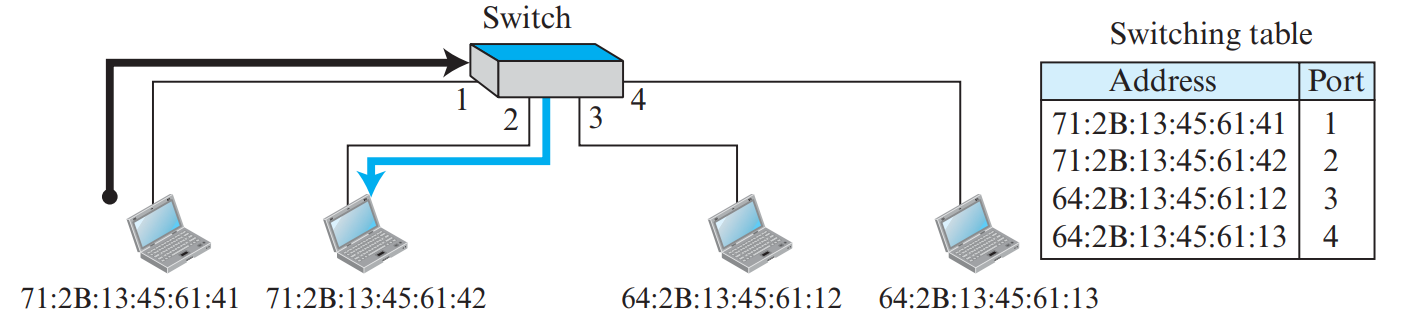
Figure 7.2: Logical Division of Physical Switch Ports into Separate VLANs (Page 42)
Advantages of VLANs
- Confining Broadcast Traffic: Routers are normally needed to contain broadcasts; VLANs divide a physical switch into multiple logical broadcast domains, dramatically reducing network congestion.
- Cost & Administration Savings: Moving an employee to a new office does not require rewiring cables—only changing switch port VLAN assignment!
- Enhanced Security: Traffic between different VLANs cannot pass directly; it must be explicitly routed through a firewall or router.
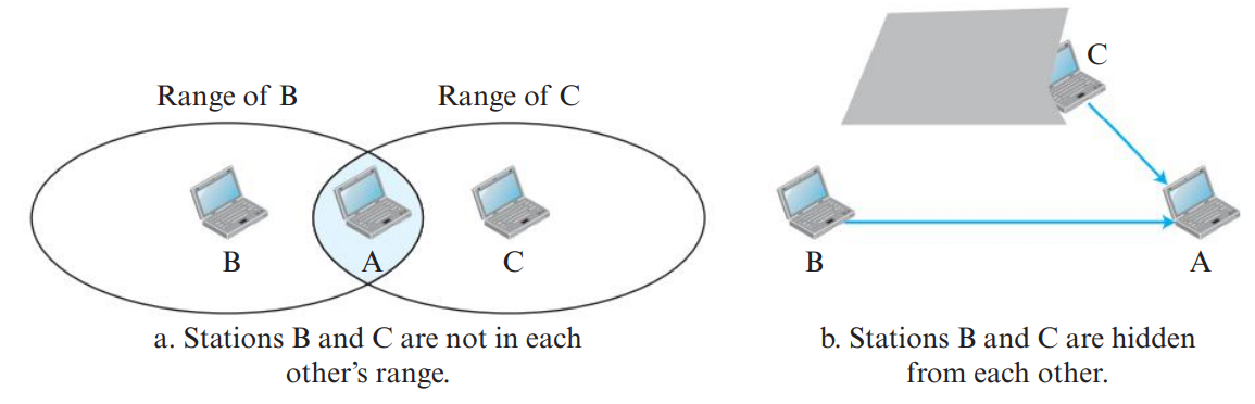
Figure 8.1: Connecting Devices and Their Operating Protocol Layers (Page 45)
| Connecting Device | Operating Layer | Functionality & Addressing | Collision & Broadcast Domains |
|---|
| Repeater / Hub |
Layer 1 (Physical) |
Regenerates and amplifies electrical signals. Broadcasts incoming bits to all other ports. Blind to MAC or IP addresses. |
1 Collision Domain.
1 Broadcast Domain. |
| Bridge / Switch |
Layer 2 (Data Link) |
Inspects destination MAC addresses. Uses a self-learning forwarding table to forward frames selectively to the correct port. |
Separates Collision Domains (each port is its own collision domain!).
1 Broadcast Domain. |
| Router |
Layer 3 (Network) |
Inspects destination IP addresses. Routes packets between different logical networks. Changes MAC addresses at each hop! |
Separates Collision Domains.
Separates Broadcast Domains! |
How a Link-Layer Switch Learns MAC Addresses
- Frame Arrival: Frame arrives at Port 1 with Source MAC \(S\) and Destination MAC \(D\).
- Learning Step: Switch inspects Source MAC \(S\) and records in its table:
MAC S -> Port 1.
- Forwarding Step: Switch checks table for Destination MAC \(D\):
- If found: Forwards frame out *only* that destination port (Filtering/Forwarding).
- If NOT found (or Broadcast): Floods the frame out all ports except the arrival port!
💡 Why Can't Wireless Networks Use CSMA/CD?
In wireless transmission, signal energy attenuates drastically with distance. A transmitting station's own outgoing signal completely drowns out any faint collision signals from distant stations. Furthermore, stations may be out of radio range of each other! Hence, wireless networks use CSMA with Collision Avoidance (CSMA/CA) instead.
1. The Hidden and Exposed Station Problems
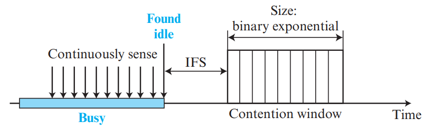
Figure 9.1: Hidden Station Problem and Exposed Station Problem in Wireless LANs (Page 48)
| Problem Name | Cause & Scenario | Consequence & Remedy |
|---|
| Hidden Station Problem |
Stations B and C can both reach Base Station A, but B and C are hidden from each other (out of mutual radio range). Both sense channel as idle and transmit to A simultaneously. |
Collision at A! Solved using RTS (Request to Send) and CTS (Clear to Send) control handshake frames. |
| Exposed Station Problem |
Station C hears Station B transmitting to A. C wants to transmit to D (which is far away from B and A). Hearing B, C unnecessarily defers transmission. |
Wasted channel capacity! C could have transmitted to D without causing interference. RTS/CTS alerts C that it can safely transmit. |
2. IEEE 802.11 CSMA/CA Protocol Timeline
Before transmitting, a station waits an Interframe Space (IFS). IEEE 802.11 defines different IFS durations to prioritize control frames over data: SIFS < PIFS < DIFS < EIFS.
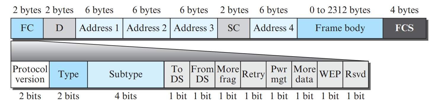
Figure 9.2: CSMA/CA Protocol Timeline: DIFS, RTS, SIFS, CTS, NAV, Data, ACK (Page 51)
- Sender senses channel. When idle for duration of DIFS (Distributed IFS), sender transmits an RTS (Request to Send) frame containing the requested transmission duration.
- Destination receives RTS and waits a short SIFS (Short IFS), then replies with a CTS (Clear to Send) frame.
- Network Allocation Vector (NAV): All neighboring stations hearing the RTS or CTS set a timer called NAV and remain silent for that entire reserved period!
- Sender transmits data frame; Destination confirms with an ACK after SIFS.
📡 IEEE 802.11 Physical Layer Standards
| Standard | Frequency Band | Modulation Scheme | Maximum Data Rate |
|---|
| 802.11 (Legacy) | 2.4 GHz ISM | FHSS or DSSS | 1 to 2 Mbps |
| 802.11b | 2.4 GHz ISM | HR-DSSS (DSSS) | 11 Mbps |
| 802.11a | 5 GHz U-NII | OFDM | 54 Mbps |
| 802.11g | 2.4 GHz ISM | OFDM | 54 Mbps |
| 802.11n | 2.4 & 5 GHz | MIMO-OFDM | Up to 600 Mbps |
3. Bluetooth Architecture: Piconet & Scatternet
Bluetooth (IEEE 802.15.1) is a short-range wireless Personal Area Network (PAN) technology operating in the 2.4 GHz ISM band using Frequency Hopping Spread Spectrum (FHSS with 1600 hops/s).
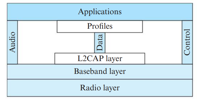
Figure 9.3: Bluetooth Piconet (1 Master, 7 Slaves) and Scatternet Architecture (Page 56)
- Piconet: An ad-hoc network consisting of 1 Primary (Master) node and up to 7 active Secondary (Slave) nodes. Communication is strictly master-slave; slaves cannot talk directly to each other. (Up to 255 parked nodes can be synchronized).
- Scatternet: Formed when two or more independent piconets overlap. A device can act as a secondary in one piconet and a primary (or secondary) in another, acting as a bridge to forward data between piconets.
📶 Bluetooth Protocol Architecture: Radio, Baseband & L2CAP
- Radio Layer: Operates in the 2.4 GHz ISM band. Uses Frequency-Hopping Spread Spectrum (FHSS) with 79 channels hopping at 1600 hops/second to avoid Wi-Fi interference.
- Baseband Layer: Manages physical links, timing, frequency hopping, and TDMA time-slot polling between Master and Slave devices.
- L2CAP (Logical Link Control and Adaptation Protocol): Adapts upper-layer protocols to the baseband. Provides protocol multiplexing, segmentation and reassembly (SAR) for packets up to 64 KB, and QoS.
💡 Why Do We Need Mobile IP?
In standard IP routing, an IP address is strongly tied to a physical network prefix (the NetID). If a laptop moves to a foreign network and retains its original IP address, routers cannot route packets to it. If it changes its IP address, all active TCP connections break. Mobile IP allows a mobile host to migrate between different networks while keeping its permanent IP address!
1. Key Entities in Mobile IP
| Entity | Role & Functionality |
|---|
| Mobile Node (MN / Mobile Host) | The node that moves its point of attachment from its home network to foreign networks without changing its IP address. |
| Home Network | The permanent home IP subnet where the mobile host's permanent IP address belongs. |
| Home Agent (HA) | A router on the home network that acts as the proxy guardian for the mobile host when it is roaming away from home. |
| Foreign Network | The visited network where the mobile host is currently located. |
| Foreign Agent (FA) | A router on the foreign network that provides routing and forwarding services to visiting mobile hosts. |
| Home Address | The permanent 32-bit IP address assigned to the mobile host. Never changes! |
| Care-of Address (COA) | A temporary IP address associated with the mobile host's current physical point of attachment in the foreign network. (Usually the IP address of the Foreign Agent). |
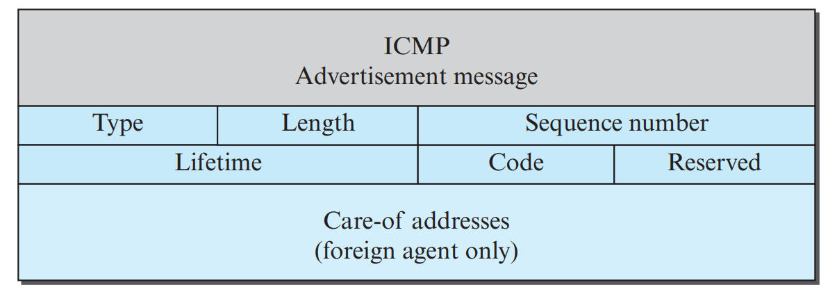
Figure 10.1: Mobile IP Architecture: Triangular Routing and Tunneling (Page 62)
2. The Three Phases of Mobile IP Operation
-
Phase 1: Agent Discovery:
- Foreign Agents and Home Agents periodically broadcast ICMP Agent Advertisement messages to announce their presence and Care-of Addresses.
- Alternatively, a freshly connected mobile host broadcasts an Agent Solicitation message asking for local agents.
-
Phase 2: Registration:
- Mobile Host sends a Registration Request to the Foreign Agent containing its Home IP, Home Agent IP, and requested lifetime.
- Foreign Agent relays the request to the Home Agent.
- Home Agent verifies credentials, binds the Mobile Host's Home IP to the temporary Care-of Address (COA) in its binding table, and returns a Registration Reply through the FA to the MH.
-
Phase 3: Data Transfer (Triangle Routing / Triangular Routing & Tunneling):
- Step 1: A Correspondent Host (CH) sends an ordinary IP packet to the Mobile Host's Home Address. Standard routers route it to the Home Network.
- Step 2 (Proxy ARP & Interception): The Home Agent intercepts the packet using Proxy ARP (answering with its own MAC address).
- Step 3 (Tunneling / Encapsulation): The Home Agent encapsulates the entire original IP packet inside a new outer IP datagram with destination address set to the Care-of Address (COA), and forwards it across the Internet (Tunneling).
- Step 4 (Decapsulation): The Foreign Agent receives the outer datagram, strips the outer header, and delivers the original packet to the Mobile Host.
- Step 5 (Direct Return Path): The Mobile Host sends reply packets directly to the Correspondent Host through standard routing without passing through the Home Agent!
⭐ Inefficiency of Triangular Routing: The Double Crossing Problem
Because packets from the Correspondent Host must first travel to the Home Agent before being tunneled to the Foreign Agent, this indirect path forms a triangle (Triangular Routing). If the Correspondent Host and the Mobile Host are located in the exact same foreign city (e.g., Kochi) while the Home Agent is in New York, packets travel all the way from Kochi to New York and back to Kochi! This is known as the Double Crossing Problem.
📐 Master Numerical 1: Cyclic Redundancy Check (CRC-3)
Problem: Given dataword 100100 and divisor polynomial \(G(x) = x^3 + x^2 + 1\). Find the codeword, and show receiver verification when received with no error.
Solution:
- Generator \(G(x) = x^3 + x^2 + 0x + 1 \implies \mathbf{1101}\) (Degree 3).
- Append 3 zeros to dataword:
100100000.
- Modulo-2 division of
100100000 by 1101 yields Remainder = \(\mathbf{001}\).
- Codeword = \(\text{Data} + \text{Remainder} = 100100 + 001 = \mathbf{100100001}\).
- Receiver divides
100100001 by 1101; Remainder = \(\mathbf{000}\) \(\implies\) Accepted!
📐 Master Numerical 2: CSMA/CD Minimum Frame Size
Problem: A network has a bandwidth of 100 Mbps and a maximum distance between stations of 1 km. The signal propagation speed through the cable is \(2 \times 10^8\text{ m/s}\). Calculate the minimum frame size required for CSMA/CD.
Solution:
- Propagation time \(T_p = \frac{\text{Distance}}{\text{Speed}} = \frac{1000\text{ m}}{2 \times 10^8\text{ m/s}} = 5 \times 10^{-6}\text{ s} = 5\ \mu\text{s}\).
- Minimum transmission time \(T_{fr} = 2 \times T_p = 2 \times (5 \times 10^{-6}\text{ s}) = 10\ \mu\text{s}\).
- Minimum frame size:
\[L_{\text{min}} = 2 \times T_p \times \text{Bandwidth} = (10 \times 10^{-6}\text{ s}) \times (100 \times 10^6\text{ bps}) = 1000\text{ bits} = \mathbf{125\text{ bytes}}\]
KTU Module 3 Comprehensive Question Bank
Answer:
- Hub: Operates at Layer 1 (Physical Layer). Regenerates electrical signals and broadcasts bits to all ports blindly without inspecting addresses. (Single collision domain).
- Switch: Operates at Layer 2 (Data Link Layer). Inspects 48-bit MAC addresses and forwards frames selectively to the destination port using a self-learning table. (Separates collision domains).
- Router: Operates at Layer 3 (Network Layer). Inspects 32-bit IP addresses and routes packets across different subnets. (Separates both collision and broadcast domains).
Answer Blueprint:
- Architecture (3 Marks): Draw and explain the Basic Service Set (BSS) (ad-hoc vs infrastructure with Access Point) and Extended Service Set (ESS) connected via a Distribution System (DS).
- Why CSMA/CA (1 Mark): State that wireless stations cannot detect collisions (CSMA/CD impossible) due to signal fading and hidden terminal issues.
- Interframe Spaces (1.5 Marks): Explain SIFS (highest priority for ACK/CTS), PIFS (PCF polling), and DIFS (DCF transmission).
- CSMA/CA Protocol Timeline (3.5 Marks): Draw the timing diagram showing:
- DIFS sensing & back-off.
- RTS transmission containing duration.
- SIFS delay & CTS reply from receiver.
- NAV (Network Allocation Vector): virtual carrier sensing where neighbors sleep.
- Data transmission & receiver ACK after SIFS.
⚡ Module 3 Last-Minute Memory Mnemonics
- Ethernet Frame Length: Min 64 bytes, Max 1518 bytes.
- CSMA/CD Rule: \(T_{fr} \ge 2 \times T_p \implies L_{\text{min}} = 2 \times T_p \times B\).
- ALOHA Max Throughput: Pure ALOHA = 18.4% (\(G = 0.5\)), Slotted ALOHA = 36.8% (\(G = 1.0\)).
- Hamming Distance: Detect \(s\) errors \(\rightarrow d_{\text{min}} \ge s + 1\); Correct \(t\) errors \(\rightarrow d_{\text{min}} \ge 2t + 1\).
- Bluetooth Piconet: 1 Master + Max 7 Active Slaves.
- Wireless IFS Priority: Smallest to Largest →
SIFS < PIFS < DIFS < EIFS.